|
|
ForumsSega Master System / Mark III / Game GearSG-1000 / SC-3000 / SF-7000 / OMV |
Home - Forums - Games - Scans - Maps - Cheats - Credits Music - Videos - Development - Hacks - Translations - Homebrew |
View topic - Attempting to build a Game-to-Gear WiFi adapter! But having a bumpy start :)
 |
| Author | Message |
|---|---|
|
Attempting to build a Game-to-Gear WiFi adapter! But having a bumpy start :)
|
|
Hello,
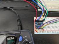
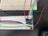
I had the idea of creating a simple WiFi interface for the Gear-To-Gear port. I have managed to directly connect two Game Gears with jumper cables and it's working fine, but as soon as I try to decouple them it stops working. My ultimate goal is to install a Raspberry Pi Pico or an ESP32 and connect them through WiFi or ESP NOW! using MicroPython. I have three intermediary steps towards my goal: 1. Directly connect with jumper wires and breadboard - WORKING 2. Connect through 2 logic converters (so that I can use 3.3V logic in the Pico/ESP32) - NOT WORKING 3. Connect throught a single Pico GPIO - NOT TRIED YET I'm stuck in step 2. The logic converters are working, I have the cables crossed the right way, but the GGs don't recognise the Gear-To-Gear connection. I attached some photos of the setup. I used GearToGearCable document in the developments section here as a reference, but the information there doesn't cover the voltages, protocol, etc. (sorry, as I'm a new member I can't share links, but you can easily find it). Does any of you know what I might be doing wrong? My next step is to get a logic analyser and see what's going on. Thank you![/url] 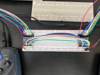
|
|
|
|
|
|
|
|
Assuming you've really convinced yourself that everything appears to be connected and configured properly (your OE pin is pulled low, you have the supplies and I/Os the right way round, etc.) then it's possible you're getting ringing on the wires that's degrading the signal enough to make it unusable. Often the combination of breadboards and long wires that you clearly have is too much for some sensitive signals.
See the following note from Sparkfun about that device:
Seems like you ought to be able to try much shorter wires with your setup with a bit of effort. You might fool around with some termination resistors but I'd definitely look at shortening your wires first. You mention a logic analyser, but if you had access to an oscilloscope you'd be able to see if there was excessive ringing. EDIT: also, just did some cursory reading on the G2G protocol, if you're only interested in serial mode then I guess the directions are only one way anyway and so to connect to a pico or something you would need very minimal level shifting, possibly just to shift the GG's TX pin down to 3.3v, which you could do with a voltage divider? |
|
|
|
|
|
|
|
Thank you willbritton for you clear reply!
I did think about interference between the wires, I used to have that problem with parallel ports and usually twisting the wires minimised the ringing. Thank you! Unfortuantely, I need to connect all the cables and not just TX/RX and ground :(. The reason is that the GGs do some chatting through PC0-PC4 and will only present the port as available to the game is that goes okay. So, even if no game really uses PC0-PC4 and only use TX/RX, those pins need to be connect. Thank you again! |
|
|
|
|
|
|
| As we were expecting, twisting the wires didn't fix it :) | |
|
|
|
|
|
| One concern is that the communication is effectively synchronous - the receiver is interrupted and has to handle the data immediately - and there’s no buffering, so any latency may break games. That’s obviously going to come after any hardware concerns, but it may mean things work worse as the network time goes up. | |
|
|
|
|
|
So "crosstalk" between the wires shouldn't be a problem at all here. The supply voltages are simply enormous compared with the potential induced voltages through round insulated wires. Crosstalk only really becomes a problem for very closely spaced wires or PCB traces and / or for applications where induced voltages might cause a relatively significant change in voltage levels. Twisting pairs of wires together (as you found!) will not help at all here. It really only makes sensed in situations where current is balanced in pairs of wires, such as differential modes.
Understood. Still though, I presume that there is a default direction that PC0..4 start operating in? Do they stay in that configuration? If your ultimate goal is to use an MPU like the pico you will need to be able to correctly set the direction of each GPIO at the right point in time. Without any out of band handshaking signals to set this up (although perhaps some more extensive docs could point to that), I would assume that PC0..4 do indeed have default directions, and that any change to those directions is communicated in-band by either the parallel or the serial interface. So I still wonder whether it's enough to set up simple down shifters on only those lines which you know will be sending data to the pico. EDIT: I guess also the bidirectional pins could be using use an open-drain setup to avoid any handshaking over direction. If this is the case you may not need any level shifting at all. Are there more comprehensive sources of information than the smspower article I referenced above?
I would have thought that once the basic hardware problems have been ironed out then any system based around a modern MPU and some local wireless comms wouldn't suffer from enough latency to cause a problem with the GG running at < 4MHz. Routing it over the internet would of course add some much more significant latency! |
|
|
|
|