|
|
DevelopmentSega Master System / Mark III / Game Gear |
Home - Forums - Games - Scans - Maps - Cheats - Credits |
SMSReader - Sockets
The IC sockets and cartridge connector
Now that we've built up the power supply, the next step is to solder in the IC sockets and cartridge connector, and the wire links to provide power to them.
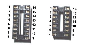
IC Sockets (2x16 pin, 1x14 pin, DIL)
Orient one of the 16 pin sockets so that pin 1 is at 12P and pin 16 is at 9P (i.e. the notch faces left). Place the other 16 pin socket so that pin 1 is at 12AB and pin 16 is at 9AB.
The 14 pin socket should be placed such that pin 1 is at 34K and pin 14 is at 37K, i.e. with the notch facing right.
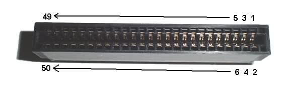
Cartridge connector (2x25 way 0.1in edge connector)
This should be placed so that pin 1 goes to 25H and pin 2 goes to 27H. (Pins 49 and 50 will be at 25AF and 27AF respectively.)
Cutting tracks
Cut tracks at the following holes:
- All holes from 10I to 10P and 10U to 10AB.
- All holes from 26H to 26P and 26R to 26AF. (Don't cut 26Q!)
- 36K, 36M, 36O, 36P, 36Q.
- 33J
- 19N
- 15U
- 13Q
Decoupling capacitors and wire links
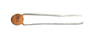
100nF Ceramic Capacitors
Solder the three 100nF ceramic decoupling capacitors in the following positions:
- 8P - 9Q
- 8AB - 9AC
- 37J - 38K
Wire links
Solder wire links between the following pairs of holes. Use solid core, insulated wire for this. For links between holes which are very close together, you can remove the insulation entirely, so long as there's no likelihood of the wire touching another bare wire or a component leg.
- 5H - 5P
- 6P - 6AB
- 13I - 12Q
- 13U - 12AC
- 14Q - 14U
- 19C - 19H
- 20I - 20N
- 21B - 21I
- 22I - 22Q
- 24Q - 24R (you can use a bare wire for this)
- 24H - 24Y
- 28Q - 28AL
- 35J - 33Q
- 39C - 39K
- 40K - 40AD
Progress so far...
Here's what your SMSReader should look like now:

< Power section | SMSReader | Data lines >
