|
|
DevelopmentSega Master System / Mark III / Game Gear |
Home - Forums - Games - Scans - Maps - Cheats - Credits |
Video Output
1986 Master System I (Sony V7040)

The earliest revisions of the model 1 Master System use a Sony V7040 video encoder chip, which takes in the RGB output from the VDP and converts it to composite video, which is sent to the RF modulator and an 8-pin DIN connector for AV output.
However, you can wire up a dedicated composite output jack if desired. Simply tap the negative lead of capacitor C28 for video, and use any nearby ground source to ground the output connector.
The V7040 also has chroma and luma outputs. These are used by the V7040 to generate composite video, but can be used for S-video output with some work. For S-video, use any generic NPN transistor and a 33 ohm resistor. Connect the V7040's luma output (pin 14) into the transistor's base, connect +5V to the collector (Pins 24 or 28), and connect the transistor's emitter to the resistor. The other end of the resistor goes to your output connector. For chroma, connect a 220 uF capacitor and 75 ohm resistor in series from pin 13 of the V7040 to your output connector. Attach your grounds to pin 12 or 18, or any other ground point on the board (such as the RF box shielding).
Consoles with this encoder output RGB that is dim compared to later revisions because Sega used different values for the resistors on the RGB signals going into the V7040. In this case, Sega used 3.3k ohm for both the series resistors and the pulldown resistors, whereas 2.2k ohm and 4.7k ohm were used for these resistors respectively on later revisions. This may have been a mistake on Sega's part as these values are correct for the BA7230LS encoder in the Mark III, which expects the amplitude of the RGB signals to be 0.7 Vpp. The V7040 and the later CXA1145 expect 1.0 Vpp, so this creates the dim RGB output on these early revisions.
To get brighter RGB, substitute R6 through R8 with 2.2k ohm resistors and R9 through R11 with 4.7k ohm resistors.
Master System II (CXA1145)
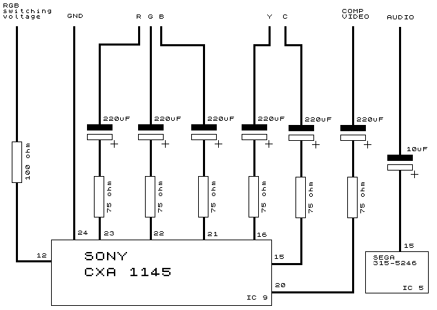
The Sony CXA1145 video chip has RGB, S-video and composite outputs. You can connect any or all of these in your mod.
Composite is on pin 20 of the CXA1145 and can be obtained in two different ways, depending on if you will be retaining the RF modulator or not. If you are keeping RF, solder a 75 ohm resistor and 220 uF capacitor in series on pin 20 of the encoder, with the negative lead of the capacitor going to your output connector. If the RF modulator is removed, the existing video circuit on the motherboard can be repurposed. On an NTSC SMS II, simply remove resistor R70 and a suitable composite signal can be tapped from where pin 2 of the RF modulator was. On PAL consoles, substitute resistor R21 with a 75 ohm resistor, remove R29 entirely and tap video from pin 2 of the modulator.
For S-Video, use any generic NPN transistor and a 33 ohm resistor. Connect the CXA1145P output into the transistor's base (Pin 15 and 16), connect +5v to the collector (Pin 12), and connect the transistor's emitter to the resistor. The other end of the resistor goes to your monitor. Attach your grounds to Pin 24 or any other ground point on the board (such as the RF box shielding).
For RGB, you will need a connection to be present for sync. Most monitors will accept the composite video signal (CXA1145 pin 20) for this. Some require a true composite sync signal - this can be obtained from pin 11. TTL sync can be taken from pin 10, but not all displays and upscalers are compatible with this. Note that if you want compatibility with Genesis/Mega Drive RGB cables, you do not need the capacitors and resistors on the RGB and sync signals and they can be wired straight through.
As shown on the schematic, the video connections are obtained from various pins on the CXA1145. On the NTSC Master System II, there are solder pads on the underside of the motherboard which are connected directly to pins 21 (green), 22 (blue) and 23 (red) of the CXA1145. On PAL Master System IIs, there are convenient vias for these signals directly in front of pins 21 through 23. These will make for a cleaner installation as opposed to soldering directly onto the encoder pins.
Audio is obtained from pin 9 of the CXA1145 or from pin 3 of the RF modulator. No extra components are required.
Finally the GND and switching voltage connections can be obtained from any ground and +5V points on the board, respectively. Pins 24 and 12 respectively of the CXA1145 are suitable.
If you're using a SCART connection, here are the appropriate pins of the plug :
| Connection | SCART pin |
|---|---|
| Red | 15 |
| Green | 11 |
| Blue | 7 |
| Composite/Sync In | 20 |
| RGB switching | 16 |
| Ground | 4, 17, 21 |
| Audio In | 2, 6 |
- Based on Mike G's guide (mirror)
Master System II (MB3514)
Later versions of the PAL SMS II, namely those with Sonic the Hedgehog built-in, have the Fujitsu MB3514 encoder instead of a CXA1145. Adding video mods on this encoder is slightly more difficult as it is a small surface-mount chip with delicate pins, but the procedure is largely the same as the MB3514 has a near-identical pinout.
Composite video and audio are handled the same way as the CXA1145, though RGB is trickier as wires must be soldered directly onto the encoder pins; there are no solder pads or vias for RGB out as before. In addition, the MB3514 does not output a 75 ohm composite sync signal on pin 11 so either composite video or TTL sync from pin 10 must be used.
However, performing an S-video mod on this encoder is considerably simpler as the MB3514 was designed to drive 75 ohm loads from its chroma and luma outputs. For both chroma and luma (pins 15 and 16 respectively), solder a 75 ohm resistor and 220 uF capacitor in series, with the negative lead of the capacitor going to your output connector.
