|
|
ForumsSega Master System / Mark III / Game GearSG-1000 / SC-3000 / SF-7000 / OMV |
Home - Forums - Games - Scans - Maps - Cheats - Credits Music - Videos - Development - Hacks - Translations - Homebrew |
View topic - Controller Port Issues
 |
| Author | Message |
|---|---|
|
Controller Port Issues
|
|
Hi,
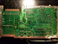
I've recently acquired a SMS and the controller ports dont function properly. The first player port generally only goes right (although sometimes I am able to go up or left, never down though) and button 1 doesn't work on port 2. I'm unsure if button 2 works on either as I haven't gotten far enough to verify that. The ports use the light phaser with no issues. This is my first time trying to fix up a console and any resources or help you could provide would be greatly appreciated. I've attached photos of the board for reference as well. 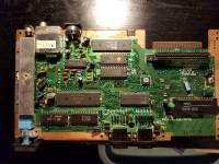
|
|
|
|
|
|
|
| are you testing the port(s) using a pad that's surely working or might it be the pad? | |
|
|
|
|
|
| I have tried multiple controllers and get the same issue regardless of controller. Issue specific to each port. I've also verified by using controllers on my genesis to confirm they are working properly. | |
|
|
|
|
|
| for any button that doesn't get registered, check continuity from the connector to the board - see this | |
|
|
|
|
Controller Port Issues
|
| Is that enough info for you to go on or do you need more specific info / guidance? | |
|
|
|
|
|
| I just bought a multimeter and tested it on the controller ports. I tested from the connector to the bottom of the board. All had continuity. Where should I check further along to test for further issues? | |
|
|
|
|
Controller Port Issues
|
|
OK, let’s start by checking the GROUND connection to the Controller Port.
Looking at each Controller Port from what would be the front of the console, the GROUND pin is pin 6 located on the bottom row of 4 pins, 3rd pin in from the left. On the board, GROUND is the exposed copper border that borders the outer edge of the board. Measuring resistance or continuity with your multimeter, there should be zero or close to zero ohms resistance between this pin and the board GROUND. Next we’ll check the signal lines from the Control Ports (or in your case confirm what you’ve measured already). For each Controller Port, starting from the top row of 5 pins, going left to right, then the bottom row of 4 pins, going left to right, the pins are UP, DOWN, LEFT, RIGHT, POWER, BUTTON1, LIGHTPHASER, GROUND, BUTTON2. With the exception of the GROUND pin and the POWER pin, each pin from the Controller Ports connects to one (and only one) pin on Gate Array chip. The Gate Array chip on your board is the chip closest to the Controller Ports labelled “SEGA 315-5216”. Looking at your board from above, the pins on the Gate Array chip on the side of the chip closest to the Controller Ports from left to right are pins 22 to 42. The UP, DOWN, LEFT, RIGHT, POWER, BUTTON1, BUTTON2 from Controller Port 1 connect to pins 25 to 30 of the Gate Array chip. The UP, DOWN, LEFT, RIGHT, POWER, BUTTON1, BUTTON2 from Controller Port 2 connect to pins 40 to 35 (descending) of the Gate Array chip. Measuring resistance or continuity with your multimeter, there should be zero or close to zero ohms resistance between each pin of the Controller Ports and its corresponding pin on the Gate Array chip. Likewise, there should not be any continuity between the Control Port pins and the pins of the Gate Array chip that they don’t belong to. Let me know how you go. This is just the start. |
|
|
|
|
|
|
|
Controller port 1 had not continuity with UP, DOWN, LEFT and BUTTON2. Controller port 2 only was missing continuity with BUTTON2. Everything else seemed to be working properly as I was testing.
I appreciate the detailed help! |
|
|
|
|
|
Controller Port Issues
|
|
Right. We're now going to narrow down where the break in continuity is for these 5 lines so we can determine what needs to be repaired.
All 5 lines go through an EM filter which is one of those small black boxes you can see on the board surrounding the Controller Ports. The EM filter has 3 legs. The middle leg is connected to ground. One of the 2 outer legs connects to the Control Ports pin and the other outer leg connects to the Gate Array chip. The button 2 lines go through a resistor as well. Here is the path these lines take: Controller Port 1 UP goes to EM11, then from EM11 to the Gate Array chip. Controller Port 1 DOWN goes to EM12, then from EM12 to the Gate Array chip. Controller Port 1 LEFT goes to EM13, then from EM13 to the Gate Array chip. Controller Port 1 BUTTON2 goes to resistor R117 which is a 330 ohm resistor, then from the resistor to EM19, then from EM19 to the Gate Array chip. Controller Port 2 BUTTON2 goes to resistor R115 which is also a 330 ohm resistor, then from the resistor to EM29, then from EM29 to the Gate Array chip. Good luck.. |
|
|
|
|
|
|
|
Controller port 1 up and left sometimes displayed full continuity but it was not consistent. Which is how the controller was also behaving. The EM filter consistently worked on both though.
Down had no continuity between port 3 and EM12 but was good elsewhere. B2 for both ports lost continuity going through their respective resistors. |
|
|
|
|
|
Controller Port Issues
|
|
For UP, LEFT and DOWN I would start by reflowing the solder joints on the controller connector and EM filters and see if that fixes it. If you cannot solder yourself find a friend or the dad of a friend that can.
For the BUTTON2 resistors, what are the resistors measuring across their legs/terminals? On the multimeters I have, the continuity setting won't beep and indicate continuity unless the resistance is less that 40 ohms. That means a 330 ohm resistor will not show continuity across it. If you have a typical multimeter that has ranges of 200, 2K, 20K, 200K... for measuring resistance, set it to 2K and measure the resistors. If the resistors measure around 330 ohm then they're fine and I would reflow the solder joints of the resistors. If the resistors are somehow open circuit or measure a large value then replace the resistors. |
|
|
|
|
|
|
| Thank you! Resistors are 330 so it looks like I'll be reflowing the solder. Any suggestions for setup to purchase? | |
|
|
|
|
Controller Port Issues
|
|
Your average $20 soldering and some solder with flux in the core will do just fine.
It's more the technique. The best thing to do is search youtube for "how to reflow solder joints" and watch a whole lot of instructional videos. Then practice on a board from some junk electronics. Once you feel like you've got it down, try the repair. |
|
|
|
|
|
|
| Thank you for all your help! It will be awhile before I fix it most likely but I'll let you know how it goes. Thanks again! | |
|
|
|