| Author |
Message |
- Joined: 28 Sep 1999
- Posts: 1197
|
SMS Display Timing
 Posted: Sun Feb 19, 2006 4:40 am Posted: Sun Feb 19, 2006 4:40 am
Last edited by Charles MacDonald on Sun Feb 19, 2006 7:16 pm; edited 1 time in total
|
I recently got a logic analyzer and have started doing some research on VDP timing, because it's one of those remaining things that I've been dying to figure out. Maybe somebody who's dedicated or insane can write an SMS emulator based on this information where everything is handled down to the per-cycle level for super accuracy. :D
I'm not specifying things in units of pixels, because then we'd get into fractional parts of a pixel and that gets messy. This way we have nice whole numbers to describe everything and no details are left to the imagination.
All tests were done on a original model NTSC SMS. The main clock in the system was measured at 10.738580 MHz. I'll refer to single cycles of that signal as 'mclk'. For reference the VDP pixel clock is half that (5.36 MHz) and the Z80, SN76489, and YM2413 clocks are one third that (3.58 MHz).
When I refer to /HSYNC and /VSYNC, these are two internally generated signals which are ANDed together and output on the VDP's /CSYNC pin. It's easy enough to tell which is which.
Frame timing:
- Each frame from the rising edge of /VSYNC pulse to the next rising edge is 179,208 mclks.
- Each scanline from the rising edge of the /HSYNC pulse to the next rising edge is 684 mclks.
This gives 262 scanlines per frame, and the frame rate is about 59.92 Hz (10.738580 MHz / 179,208 mclks)
Scanline timing:
- The active display period is 512 mclks.
- The blanking (border area) period is 172 mclks.
Frame events:
- For a frame interrupt, /INT is pulled low 607 mclks into scanline 192 (of scanlines 0 through 261) relative to pixel 0. This is 4 mclks before the rising edge of /HSYNC which starts the next scanline.
- For a line interrupt, /INT is pulled low 608 mclks into the appropriate scanline relative to pixel 0. This is 3 mclks before the rising edge of /HSYNC which starts the next scanline
Other video signal timing details
- Relative to pixel 0, the /HSYNC pulse occurs 558 mclks into the scanline.The pulse width is 53 mclks. For the remaining 73 mclks /CSYNC is high.
- The /VSYNC pulse is formed as follows: On the scanline that /VSYNC will occur, /CSYNC is forced low after 3 mclks. It remains low for the next 2052 mclks (3 scanlines) and goes high for 681 mclks (one full scanline minus the 3 mclks from the single pixel shown).
So essentially the /VSYNC pulse occupies 3 scanlines, offset by 1.5 pixels so four scanlines are used. (though time-wise it's still exactly 3 scanlines)
The official GG docs describe the point where the H counter value 'jumps backwards', which starting from pixel 0 of the scanline should be 588 mclks in. However I'd expect it to coincide with the start or end of the /HSYNC pulse (it falls right in the middle) and there is no other activity on other VDP pins there. Who knows what the VDP *really* does on the inside, but I was hoping these two things would match up.
Beyond that things like the horizontal sync and and blanking match the TMS9918 documentation which is a relief. :)
|
| |
  
|
- Joined: 28 Sep 1999
- Posts: 1197
|
Fun with the pause button
Posted: Sun Feb 19, 2006 5:26 am
|
Following up on FluBBa's pause button finding:
When the pause button is pressed, the VDP asserts /NMI at the start of line 261 (counting from 0-261 here). It happens on the rising edge of /HSYNC, which is 611 mclks into line 260 relative to pixel 0.
As long as the pause button is pressed, /NMI is asserted. When it is released, the VDP negates /NMI at the same point (start of line 261) on the next frame (or whichever following frame the button was released)
What I can't check is if pressing and releasing the button prior to line 261 prevents the NMI from happening, but I'm not sure if such a thing can be done in such a short amount of time.
I find it interesting that this particular scanline is used, but then again it's when the VDP parses sprites for line 0 and maybe does it's pre-frame tasks for various things, including debouncing the pause button.
|
| |
|
- Site Admin
- Joined: 25 Oct 1999
- Posts: 2029
- Location: Monterey, California
|
Posted: Mon Feb 20, 2006 12:22 am
|
Charles,
Very interesting information indeed. Can you confirm that I'm correct in reading that (on the tested console, at least), an NMI will -not- occur during the display area or any time during a frame other than the start of line 261? I'm playing around with using the stack pointer for processing data while interrupts are off, but it would be pretty disasterous if an NMI were to occur in the middle of one of these operations when the stack point pointing at ROM, and at least undesirable if it occured when it was pointing to some data in RAM that I didn't want overwritten.
|
| |
|
- Joined: 28 Sep 1999
- Posts: 1197
|
Posted: Mon Feb 20, 2006 12:29 am
|
Heliophobe wrote Charles,
Very interesting information indeed. Can you confirm that I'm correct in reading that (on the tested console, at least), an NMI will -not- occur during the display area or any time during a frame other than the start of line 261?
You are correct. I checked pause button up/down events and the effect on the NMI pin several times and always had consistent results. The start of line 261 is the only place NMI will be asserted or negated, regardless of when the pause button is pressed earlier in the frame.
There's actually quite a lot of noise when pause is pressed, so I can see why the debouncing was necessary. I figured you'd get a few transitions, but it looks like over 50 or so.
Quote I'm playing around with using the stack pointer for processing data while interrupts are off, but it would be pretty disasterous if an NMI were to occur in the middle of one of these operations when the stack point pointing at ROM, and at least undesirable if it occured when it was pointing to some data in RAM that I didn't want overwritten.
I'd say if you can finish everything up before the next frame, you'd be set. Or print a message warning the user to never, ever press pause. :)
|
| |
|
- Joined: 31 Jan 2006
- Posts: 71
|
Posted: Mon Feb 20, 2006 8:34 am
|
Great info :)
Let me ask some "newbe" questions..
Quote
- Each frame from the rising edge of /VSYNC pulse to the next rising edge is 179,208 mclks.
- Each scanline from the rising edge of the /HSYNC pulse to the next rising edge is 684 mclks.
This gives 262 scanlines per frame, and the frame rate is about 59.92 Hz (10.738580 MHz / 179,208 mclks)
How do you exactly work out the number of scanlines??
And the active/blanking display period?
|
| |
|
- Joined: 28 Sep 1999
- Posts: 1197
|
Posted: Mon Feb 20, 2006 3:42 pm
|
patroclus wrote Great info :)
How do you exactly work out the number of scanlines??
It's the total clocks in between the /VSYNC pulse (which is one frame) divided by the number of clocks per scanline , which ends up being 179208/684 = 262.
Quote And the active/blanking display period?
The VDP has a pin called Y1 which goes high when the screen is blanked or when opaque pixels are shown, and low for transparent pixels. I used that to see the 'width' of the border and active display area.
|
| |
|
- Joined: 21 Jul 2005
- Posts: 412
- Location: GBG
|
Posted: Mon Feb 20, 2006 11:18 pm
|
Nice work!
I had hoped you would do something like this =)
But we still don't know when the scanline register changes, or? is it even possible to figure that out?
Charles MacDonald wrote
Frame events:
- For a frame interrupt, /INT is pulled low 607 mclks into scanline 192 (of scanlines 0 through 261) relative to pixel 0. This is 4 mclks before the rising edge of /HSYNC which starts the next scanline.
- For a line interrupt, /INT is pulled low 608 mclks into the appropriate scanline relative to pixel 0. This is 3 mclks before the rising edge of /HSYNC which starts the next scanline
Based on my tests frame interrupt allways happens 1 cpu clock before a corresponding line interrupt, does this mean that we know where the masterclock is divided to get the cpu clock?
Also the NMI is generated on the beginning of the last line, that is, line 312 on a PAL console.
Oh, if you need anything tested on PAL console just let me know. =)
|
| |
|
- Joined: 28 Sep 1999
- Posts: 1197
|
Posted: Tue Feb 21, 2006 12:49 am
|
FluBBa wrote Nice work!
I had hoped you would do something like this =)
But we still don't know when the scanline register changes, or? is it even possible to figure that out?
Thanks, the PCE is next, as you can guess. :) I'll check out where the scanline counter changes sometime this week. It won't be precise as the Z80 polling loop adds some overhead.
Currently I execute a HALT instruction after a polling loop; it's 4 T-states (12 mclks) long and the Z80 asserts /HALT 10 mclks in. So far this seems like the fastest way for the Z80 to trigger the logic analyzer and start sampling data.
Quote
Based on my tests frame interrupt allways happens 1 cpu clock before a corresponding line interrupt, does this mean that we know where the masterclock is divided to get the cpu clock?
The VDP divides the master clock by 3 for the Z80 clock, is that what you were asking? The Z80 clock isn't symetrical, for the first master clock cycle it is high, then low for the remaining two. This way it occupies exactly three master clock cycles.
Quote
Also the NMI is generated on the beginning of the last line, that is, line 312 on a PAL console.
Oh, if you need anything tested on PAL console just let me know. =)
Thanks! I have a PAL switch on my SMS2, I wonder if the results from that would be similar enough to a real PAL console; the VDP would be operating just as it would in a PAL console, but at the wrong frequency.
Regardless I'll have to do all these checks again on the SMS 2 just to see what's different. :\
|
| |
|
- Site Admin
- Joined: 19 Oct 1999
- Posts: 14745
- Location: London
|
Posted: Tue Feb 21, 2006 8:53 am
|
|
Isn't it about time we sent Charles a real PAL SMS?
|
| |
|
- Site Admin
- Joined: 08 Jul 2001
- Posts: 8653
- Location: Paris, France
|
Posted: Tue Feb 21, 2006 10:13 am
|
Maxim wrote Isn't it about time we sent Charles a real PAL SMS?
Anybody who need hardware/software for useful purposes, e-mail me with your request/address and I can probably send you something free of charge sooner or later.
|
| |
|
- Joined: 01 Feb 2004
- Posts: 1464
- Location: Sunny ol Tamworth, New England NSW AU
|
Posted: Tue Feb 21, 2006 10:15 am
|
|
Well I got a spare PAL SMS 2 board thats in working order, you could have it for free, I was modding my case but I stuffed it up so I threw it in the bin.
|
| |
|
- Joined: 21 Jul 2005
- Posts: 412
- Location: GBG
|
Posted: Tue Feb 21, 2006 5:44 pm
|
Charles MacDonald wrote Thanks, the PCE is next, as you can guess. :)
Oooooh, sweet.
What I meant where the mclock is divided was that we should now know which mclock corresponds to which pixel which corresponds to which cpu clock.
One could make a nice picture of the most important times in the border towards the first pixel with all three clocks.
|
| |
|
- Joined: 28 Sep 1999
- Posts: 1197
|
Posted: Tue Feb 21, 2006 7:54 pm
|
FluBBa wrote Charles MacDonald wrote Thanks, the PCE is next, as you can guess. :)
Oooooh, sweet.
What I meant where the mclock is divided was that we should now know which mclock corresponds to which pixel which corresponds to which cpu clock.
One could make a nice picture of the most important times in the border towards the first pixel with all three clocks.
I guess I am not seeing what the need for this would be.
For example when I say the active display is 512 mclks long, you can tell that the next pixel shown shown is 256 (0-255 having just been displayed), and the Z80 will be in the middle of cycle 170.
It's not like the clock are out of phase (like they started with random values or something), they have a fixed layout like this:
-_-_-_-_-_-_ : 6 mclk cycles
--__--__--__ : 3 pclk cycles
--____--____ : 2 zclk cycles
Does that make sense? Or I can make a picture anyway if that helps.
|
| |
|
- Joined: 21 Jul 2005
- Posts: 412
- Location: GBG
|
Posted: Tue Feb 21, 2006 9:09 pm
|
What I was trying to say is that the line interrupt and the frame interrupt never happens on the "same" cpu clock they are allways 1 cpu clock apart (compared from their respective raster line). Even though there is only 1 mclock between them they can never be executed on the same cpu clock.
I hope that that makes more sense =)
1 2
_--__--__--__--__--__--__ ; mclk
_----____----____----____ ; pclk
_----________----________ ; zclk
1=line interrupt
2=frame interrupt
|
| |
|
- Joined: 28 Sep 1999
- Posts: 1197
|
Posted: Mon Feb 27, 2006 4:48 am
|
FluBBa wrote Nice work!
I had hoped you would do something like this =)
But we still don't know when the scanline register changes, or? is it even possible to figure that out?
When checking for a transition on the scanline counter, the earliest point at which an I/O read cycle will read the new scanline value is 12 mclks (4 Z80 cycles) prior to the rising edge of the horizontal sync pulse on the /CSYNC pin.
For example for an 'in a, (c)' instruction which is 36 mclks (12 Z80 cycles) long, the third machine cycle must coincide such that /CSYNC goes high at the same time the cycle finishes.
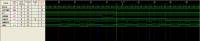
I've attached a timing diagram to illustrate this:
A to B are the two machine cycles (12 mclks each) used to fetch the opcode bytes for 'in a, (c)'.
B to C is the I/O read cycle (12 mclks). Note that it finishes at the same time /CSYNC goes high.
C to D is the following 'jr nz, -' instruction (12 mclks for fetching the opcode, 9 mclks for the displacement byte)
D to T is the first 10 mclks of the 12-mclk 'halt' instruction, T is the point that HALT goes low.
It seemed odd to me that the scanline counter would change before the rising edge on /CSYNC, but I would imagine there could be internal delays from between the time the horizontal sync pulse is generated and when that actually appears on the VDP pin. I would have assumed the earliest point would be during or immediately after the rising edge.
Anyway, if the I/O cycle occurs any earlier, the scanline counter hasn't changed and the polling loop will fall through on the next pass.
Still looking at the interrupt stuff btw, it's taking longer than expected to figure out...
|
| |
|
- Joined: 21 Jul 2005
- Posts: 412
- Location: GBG
|
Posted: Mon Feb 27, 2006 7:49 pm
|
Charles MacDonald wrote
It seemed odd to me that the scanline counter would change before the rising edge on /CSYNC
But didn't the line interrupt occur 3 mclks before the HSync? Doesn't that make sense then that both happens at the same time =)
The IOREQ is held for a couple of cycles while the VDP outputs the data, if you move the window 3 mclks to the left in your diagram it misses the spot where the lineinterrupt happens doesn't it?
|
| |
|
- Joined: 28 Sep 1999
- Posts: 1197
|
Posted: Mon Feb 27, 2006 11:30 pm
|
Quote But didn't the line interrupt occur 3 mclks before the HSync? Doesn't that make sense then that both happens at the same time =)
Aha, that's absolutely correct. Well, I guess it means all the timing agrees with each other, and that's certainly a good thing.
Quote ]The IOREQ is held for a couple of cycles while the VDP outputs the data, if you move the window 3 mclks to the left in your diagram it misses the spot where the lineinterrupt happens doesn't it?
Yes. I wish I could get the Z80 timing a little more precise so I could position the /IORQ pulse closer to the horizontal sync edge, but given limitations of the hardware I think this is close enough.
Was there anything I needed to test apart from the timing details of having a line interrupt and frame interrupt occur at the same time?
|
| |
|
- Joined: 21 Jul 2005
- Posts: 412
- Location: GBG
|
Posted: Wed Mar 01, 2006 9:30 pm
|
I don't think I have anything else right now that I've any questions about.
I will do some test myself on the instructions that affect IXH and IXL, MAMEs z80 has some strange timings.
|
| |
|
- Joined: 21 Jul 2005
- Posts: 412
- Location: GBG
|
Posted: Thu Mar 02, 2006 11:55 am
|
Oh, there is one thing.
What happens if you read the VPD status register at the same time as a frame IRQ is set? I know for a fact that the GG game Chicago Syndicate must be able to read the frame IRQ flag (at least a couple of times) while frame IRQs are enabled at the same time.
What could be nice to know is if the IRQ is taken even after the status is read (this I can test this myself).
More interesting though is if you can wave your magic over some of the finer details of how the IRQline works here, ie. it's probably lowered at the same time as the flag is set but is it reset straight afterwards or do you need to read the register again to reset it?
|
| |
|
- Joined: 23 Feb 2007
- Posts: 18
|
Posted: Fri Feb 23, 2007 11:33 am
|
Hi,
I know it's not a Genesis board but I can't find any info on genesis vdp timing anywhere else, except in previous Charles's documents (genvdp.txt & m5hvc.txt i would say)
Could these timings applie to the Genesis VDP also ? I mean, considering that a scanline is 488clks rather than 684 here, could we apply this ratio to your sms timings in order to find the genesis ones ?
I think it would be useful in emulator coding since I found that a lot of games are very timing sensitive (hblank, hsync and vsync especially)
|
| |
|
- Joined: 28 Mar 2002
- Posts: 180
- Location: Toronto, Canada
|
Re: Fun with the pause button
Posted: Fri Feb 23, 2007 3:57 pm
|
Charles MacDonald wrote What I can't check is if pressing and releasing the button prior to line 261 prevents the NMI from happening, but I'm not sure if such a thing can be done in such a short amount of time.
Can't you do this by setting up a line interrupt in the middle of the screen and using this signal to trigger the pause button on and off? Since you can control the release of the /INT line (by reading the control port) it's possible to control the timing and press/release the pause button.
I was wondering. Maybe the debouncing circuit is there also to prevent this situation, not only to filter the noise generated by the eletric contacts.
|
| |
|
- Joined: 28 Mar 2002
- Posts: 180
- Location: Toronto, Canada
|
Posted: Fri Feb 23, 2007 4:12 pm
|
FluBBa wrote What could be nice to know is if the IRQ is taken even after the status is read (this I can test this myself).
More interesting though is if you can wave your magic over some of the finer details of how the IRQline works here, ie. it's probably lowered at the same time as the flag is set but is it reset straight afterwards or do you need to read the register again to reset it?
I agree. It will be nice to know the exact timing on this. My guess is that when the control port is read, the internal flags will disable the /INT line immediately. This makes sense, since when the interrupts are disabled in VDP (by setting the appropriate registers) and there is a pending interrupt, enabling interrupts will assert the line immediately.
|
| |
|
- Joined: 28 Mar 2002
- Posts: 180
- Location: Toronto, Canada
|
Posted: Wed May 02, 2007 1:44 pm
|
Charles MacDonald wrote
- For a frame interrupt, /INT is pulled low 607 mclks into scanline 192 (of scanlines 0 through 261) relative to pixel 0. This is 4 mclks before the rising edge of /HSYNC which starts the next scanline.
- For a line interrupt, /INT is pulled low 608 mclks into the appropriate scanline relative to pixel 0. This is 3 mclks before the rising edge of /HSYNC which starts the next scanline
Charles!!
Regarding this information about interrupt timing. I was reading an old post (http://www.smspower.org/forums/viewtopic.php?t=2381) about frame interrupts and line interrupts being triggered at the same time.
benryves pointed out some VDP bugs in the C# port and i'm still confused about the exact timing on this.
For lines 0 to 261
:: Until line 192 (0..192) >> Line counter is decremented (if zero, Pending line INT flag is set)
:: On line 192 >> Pending frame INT flag is set
:: After line 192 (193..261) >> Line counter is reloaded
To assert the line, i'm using the following code:
intline = (pendingframe & frameenable) | (pendingline & lineenable);
So, it seems correct, since when Z80 reads the status port, it will clear both flags and release the line immediately (this code to assert the line is executed everytime before the cpu executes an instruction, as interrupts are checked between instructions).
But this approach is still causing problems. The top row of Road Rash's title doesn't scroll in (it's already there and the rest of the rows scroll in underneath it) and the SMSPower 7th Anniversary demo (first release) is still freezing.
Any ideas?
|
| |
|
- Joined: 12 Apr 2005
- Posts: 391
- Location: London, United Kingdom
|
Posted: Wed May 02, 2007 2:20 pm
|
|
Most of my own VDP interrupt timing problems actually came from bugs in my Z80 emulation, not the VDP itself. I don't know how helpful that is to know, though. :-(
|
| |
|
- Joined: 28 Mar 2002
- Posts: 180
- Location: Toronto, Canada
|
Posted: Wed May 02, 2007 5:34 pm
|
benryves wrote Most of my own VDP interrupt timing problems actually came from bugs in my Z80 emulation, not the VDP itself. I don't know how helpful that is to know, though. :-(
Makes sense. That's the big issue when porting systems, you will always see "bad" code suitable for optimizations and refactoring. My current Z80 core in C# sounds better than the previous one written for Delphi, and i've changed the way to process interrupts.
My old VDP implementation had a method to return the "interruptline" status, and this was updated on every emulated scanline. If the Z80 code reads the status port, the flag will be cleared, but since the "interruptline" will be updated only in the next scanline, further interrupts may occur. Now, it affects the "interruptline" immediately, so this may be the cause.
|
| |
|
|
Julian
|
Posted: Tue Oct 02, 2007 1:22 pm
|
Charles MacDonald wrote
All tests were done on a original model NTSC SMS. The main clock in the system was measured at 10.738580 MHz. I'll refer to single cycles of that signal as 'mclk'. For reference the VDP pixel clock is half that (5.36 MHz) and the Z80, SN76489, and YM2413 clocks are one third that (3.58 MHz).
When I refer to /HSYNC and /VSYNC, these are two internally generated signals which are ANDed together and output on the VDP's /CSYNC pin. It's easy enough to tell which is which.
Frame timing:
- Each frame from the rising edge of /VSYNC pulse to the next rising edge is 179,208 mclks.
- Each scanline from the rising edge of the /HSYNC pulse to the next rising edge is 684 mclks.
This gives 262 scanlines per frame, and the frame rate is about 59.92 Hz (10.738580 MHz / 179,208 mclks)
thanks for this
what about PAL systems ? i imagine that the two main differences are:
- the MAIN CLOCK that is a little slower
- the VDP switched in PAL mode (313 lines per frame, approx. 50 frames/seconde)
the fact is that the scanline duration (684 mclks) is exactly 342 pixels clocks (684/2) but does the VDP also output 342 pixels per scanline on PAL mode or a little less ?
What I would like to know is what would change in the VDP between PAL and NTSC modes and what would logically remain unchanged (mclock dividers, line duration, pixel width,..) ?
Another interesting thing would be to know how similar does the genesis vdp in 32cells mode works: I mean, the main clock is known to be 53.693175 which is quite exactly 5x the SMS main clock, which let me think that the genesis pixel clock could logically be 1/10 of the main clock and that the above timings apply in 32 cell mode (in 40 cell mode, I read somewhere that the pixel clock should be something like 1/8 of the main clock)
|
| |
|
- Joined: 21 Jul 2005
- Posts: 412
- Location: GBG
|
Posted: Sat Mar 01, 2008 8:40 pm
|
Ok, I did a quick IRQ/HCount tester.
Both the IRQ and NMI routines begins with [out ($3f),A], where A is set to $FF.
Before tha irq the cpu is in halt so the actual values varies between 4 values (or in this case 3 values as $08 is repeated on 2 cycles).
The lowest values I got was:
VBlank: HC=$06 (20mclks)
HBlank: HC=$07 (21mclks)
NMI: HC=$06 (18mclks)
These values seem correct within each other (eg HBlank is 1 M cycles after VBlank and NMI is 3 M cycles after HBlank (NMI takes 11 cycles, IRQ 13)).
Counting some cycles...
The IRQ line must be set before the last cycle of the instruction, the IRQ is 13 cycles long and the out doesn't set the wr until after 7 (8?)cycles.
So that is something like 21/22 cpu cycles, so the means that the VBL happens around HC=$F6.
HC=$F6 would give something like (684-10*3) 654mclks, thats quite a bit from 607. Does this mean that the HCount values is not really synced to the display the way we thought it was?
|
| |
|
- Joined: 23 Feb 2007
- Posts: 18
|
Posted: Thu May 15, 2008 2:56 pm
|
FluBBa wrote
HC=$F6 would give something like (684-10*3) 654mclks, thats quite a bit from 607. Does this mean that the HCount values is not really synced to the display the way we thought it was?
I was thinking about these recently and think I figured the answer in the official GG documentation (see images attached)
As you can see, GG active display starts at HC=$20. As it is 160 pixels wide, there are 48 pixels offset on both side to retrieve the 256 pixels SMS display , which would give you HC=$8 for the first active pixel (from the 256 ones)
Maybe the Hcounter is taking the left border area (13 pixels, according to most docs) in account, I don't know.
Anyway, if you consider this as pixel 0 mentionned by Charles McDonald (first non-transparent pixel, apparently determined through the Y1 pin), 607 MCLk later (i.e 303-304 pixels later), you got approximately HC=$F4 or $F5 (offcial docs say that HINT and VINT occurs approx. arround $F4)
hc.gif (14.83 KB)
Hcounter values
vc.gif (12.34 KB)
Vcounter values
|
| |
|
- Joined: 21 Jul 2005
- Posts: 412
- Location: GBG
|
Posted: Thu May 15, 2008 9:07 pm
|
That would explain a couple of things, I remember I saw the numbers in the docs but I didn't react to it one bit. I just thought, hey it starts at 0x20, 'cause that's where the GG screen starts.
But thats 64 pixels from 0, so thats actually 16 pixels too much.
Anyway, great find! =)
|
| |
|
- Joined: 23 Feb 2007
- Posts: 18
|
Posted: Fri May 16, 2008 3:57 pm
|
Yes, that's strange, i thought that logically HC=0 would correspond to the first drawn pixel (including the backdrop color) but it seems indeed to be 3 pixels before
Or maybe the docs are wrong and the left border is 16 pixels, not 13, but it seems to have been confirmed by Charles McDOnald from his personal doc
|
| |
|