|
|
DevelopmentSega Master System / Mark III / Game Gear |
Home - Forums - Games - Scans - Maps - Cheats - Credits |
YM 2413 Reverse Engineering Notes 2015 - 12 - 31
by andete. Original documents available at: https://github.com/andete/ym2413/tree/master/results
<< YM2413 Reverse Engineering Notes 2015-12-24 | YM2413 Reverse Engineering Notes | YM2413 Reverse Engineering Notes 2016-02-10 >>
Introduction
In this post we'll look in more detail at the ADSR envelopes. In an earlier post we've already studied the decay-/release- and attack-rate in isolation. This post will focus more on the overall shape of the envelope and the parameters that influence it.
These settings have a major influence on the ADSR envelope:
- AR: attack rate
- DR: decay rate
- RR: release rate
- SL: sustain level
- EG_TYPE: chooses between percussive or sustained tone
- SUS-ON/OFF: activates sustain-rate, see below
- KEY-ON/OFF: triggers transitions in the ADSR states
All will be explained in more detail below. Of these 7 settings, the first 5 are per operator, the last 2 are per channel. This also means that if you're using one of the pre-defined instruments, the first 5 parameters are fixed.
The AR, DR, RR parameters were already studied in detail before. They set the basis attack, decay- or release-rate. This (4-bit) rate is still combined with the KSR and frequency settings to get a (6-bit) effective rate. We already know how this effective rate influences the (7-bit) envelope level over time.
We looked at the SL parameter in the last post. It selects a specific envelope level using this simple formula:
internal-sustain-envelope-level = 8 * SL
The KEY-ON/OFF parameter we've already used many times in our experiments but never yet studied in detail. And we haven't yet looked at the EG_TYPE and SUS-ON/OFF parameters at all.
The typical ADSR envelope diagrams
To start I've copied the typical envelope diagrams found in the YM2413 application manual. I did add some annotations which I'll explain below.

The first observation is that there are 2 diagrams. Both have a slightly different overall shape. Which of these 2 is active depends on the 'EG_TYPE' bit:
- EG_TYPE = 0: Percussive Tone
- EG_TYPE = 1: Sustained Tone
The main difference between these two is what happens when the decay phase (DR) reaches the sustain level (SL). In case of a sustained tone, the envelope remains at the SL level until a key-off event. In case of a percussive tone, after reaching SL, we immediately go to the release phase (RR).
Each of the 2 diagrams has a (colored) line divided in different segments (each segment has a label like DP, AR, DR, SL, RR, RR' RS). Every segment describes a curve between 0dB (top) and -48dB (bottom). From earlier posts we know this range (0..-48dB) is divided in 128 steps (0.375dB/step). (In contrast on Y8950 the range goes from 0..-96dB in steps of 0.1875dB).
Directly below the (colored) envelope curve is another (black) curve that indicates the status of the KEY-ON/OFF bit. Changes in this bit can trigger transitions in the envelope curve.
Let's now go separately over these two diagrams in more detail.
1) Percussive Tone
Let's go from left to right over the (colored) envelope curve. Assume we start with KEY-OFF in the RR' phase (brown). We'll come back to this state later.
At some point KEY changes OFF->ON. The envelope goes to the 'damp' phase (DP, purple). In this phase the envelope rapidly goes down. The YM2413 application manual has very little to say about this phase. About the only thing (in very small print) it says is that a 0..-48dB transition in the DP-phase takes 10ms. I measured this and found that the DP phase corresponds to a base decay-rate of '12'. This indeed corresponds to a 0..-48dB time of 10.22ms. I checked that for higher frequencies the rate is faster, just as it is for all the other rates according to the formula: effective-rate = base-rate + Rks (see earlier post). In other words the damp-phase behaves just like a decay- or release-phase with basis rate=12.
After a (short) while the DP phase ends and we enter the attack-phase (AR, blue). The picture suggests DP ends when the envelope reaches -48dB, but my early measurements show it's closer to something like -45dB. I still need to investigate this in more detail.
The attack curve is the only segment in this diagram that is not a straight line. But remember that the Y-axis is using a logarithmic scale. When looking at the amplitude on a linear scale, the attack rate actually follows roughly a linear course (approximated with stair steps). On a linear scale, the other segments are exponentially decaying curves. The attack curve itself has been investigated in an earlier post, though not everything about it is completely clear yet.
When the envelope reaches 0dB we enter the decay phase (DR, in red). In this phase the envelope goes down again. This curve has also been studied before.
When the envelope reaches the sustain level (SL) we switch from the decay phase (DR) to the release-phase (RR, cyan). In the diagram this is a slower rate (the typical case I think?), but it could just as well be set to a faster or an equally fast rate.
The release-phase continues until KEY changes ON->OFF (but can't go lower than -48dB). At that point a 2nd release phase is entered. In the diagram this phase is indicated by the brown RR' or by the stippled RS segment. Which of these two segments is selected depends on the SUS-ON/OFF bit. SUS-ON selects the RS curve with a basis-rate=5. SUS-OFF selects RR' with basis-rate=7. In both cases there is KSR-correction applied to get to the effective-rate.
When KEY switches OFF->ON we restart this diagram from the left. Note that only the phases AR, DR and RR have a configurable (4-bit) rate. The other phases, DP(=12), RR'(=7) and RS(=5), have a fixed basis-rate. In all cases KSR-correction is applied.
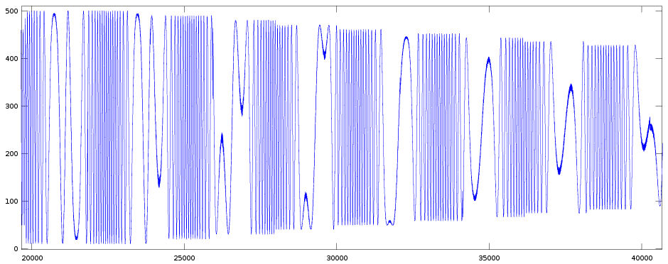
Just to show that I'm not making things up :-) I'll show an image obtained from measurements on a real YM2413 of a percussive tone.

It was created with these settings:
| Operator | AM | PM | EG | KR | ML | KL | TL | WF | FB | AR | DR | SL | RR |
|---|---|---|---|---|---|---|---|---|---|---|---|---|---|
| modulator | 0 | 0 | 1 | 0 | 00 | 0 | 63 | 0 | 0 | 15 | 00 | 00 | 00 |
| carrier | 0 | 0 | 0 | 0 | 08 | 0 | 0 | 05 | 06 | 02 | 04 |
| reg#0x10 = 0x80 | fnum=0x080 |
| reg#0x30 = 0x00 | max volume / custom instrument |
| reg#0x20 = 0x13 | key-on / block=1 |
after some delays KEY was switched OFF, ON and back OFF
From left to right you see:
- At x=0 we see the release phase of the previous note, we have KEY=OFF.
- Around x=1000 we switch KEY=ON, this enters the damp phase, that only takes a few hundred samples, so it's difficult to see in this image.
- Between x=1300..6500 we're in the attack phase. Because the Y-axis is using a linear scale, the attack ramp is also more or less linear (though the start is a bit slower than linear).
- Until about x=10500 we're in the decay phase. The amplitude decays exponentially (though the exponential nature is not clearly visible in this segment). It lasts until we reach -6dB (selected by SL=2, -6dB is half of the maximum amplitude).
- Between about x=10500..19000, we're in the 1st release phase. Here the amplitude is slowly (also exponentially) decaying.
- At about x=19000 we switch KEY=OFF. This switches to the 2nd release phase with a much faster release rate. Here you clearly see the exponential nature of the curve (in a linear scale).
2) Sustained Tone
I'll go a bit quicker over this diagram. Suppose we start in the sustained-phase (SL, green, on the left) and KEY=ON. At some point KEY switches ON->OFF, we enter RR (I'll come back to this at the end). Soon after KEY switches back OFF->ON and we enter the damp phase (DP, purple).
So even though KEY was only OFF for a very brief moment, the envelope goes down (to about -45dB) before starting to rise again. On the other OPLx chips, setting KEY=ON immediately starts the attack phase, and the envelope rises starting from the current envelope level.
The attack- and decay-phases them self are identical for percussive and sustained tones. But there is a difference at the end of the decay-phase. Instead of going to the release phase, for a sustained tone, the envelope remains at the sustain level (SL, green) for as long as KEY=ON.
When KEY switches ON->OFF we enter the release-phase (RR, cyan). But, just like in the percussive diagram, also here there's an alternative curve (RS, stippled) that can be selected via the SUS-ON/OFF bit. For SUS-ON the basis-rate is fixed at 5, for SUS-OFF the basis rate is the selected RR-rate.
Note that only YM2413 (OPLL) has this SUS-ON/OFF bit, not the other OPLx chips. But they also don't need it: those chips don't have fixed instruments (each channel has full control over RR). So instead of flipping a bit to override the release-rate with RS=7 you could just as well select RR=7.
And here's an image from measuring this scenario on a real YM2413 with these settings (but I won't go over it):
| Operator | AM | PM | EG | KR | ML | KL | TL | WF | FB | AR | DR | SL | RR |
|---|---|---|---|---|---|---|---|---|---|---|---|---|---|
| modulator | 0 | 0 | 1 | 0 | 00 | 0 | 63 | 0 | 0 | 15 | 00 | 00 | 00 |
| carrier | 0 | 0 | 1 | 0 | 08 | 0 | 0 | 05 | 06 | 02 | 06 |

Some atypical transitions
The previous section explained the typical ADSR diagram with EG_TYPE and SUS-ON/OFF bits fixed and KEY-ON/OFF changing at 'typical' moments in time. It's often more insightful to look at the atypical cases.
I measured all the stuff below, But I'm not showing graphs because I don't think it's needed to understand the explanation and creating nice images does take quite some time.
a) Change AR, DR, RR while tone is playing.
Let's start with something easy. While a tone is playing we change the value of the AR, DR, RR settings. This behaves as expected: the change takes effect immediately. E.g. if we change DR while in the decay phase we immediately switch to that new decay rate. Immediately here does not mean that the envelope level changes immediately but that we immediately wait for a different bit to flip in the global counter (see post about the decay rate for details). And also as expected, changing DR when not in the decay phase has no effect (not until we reach the DR phase).
b1) Change SL while in the sustain phase (sustained tone, EG_TYPE=1).
This has no effect. So increasing the SL level does not make the envelope go down further until that new SL level is reached. This suggests the SL value is only used as a stop-condition for the DR phase.
b2) Change SL while in the decay phase.
In a second experiment I started with a high SL value, waited till the envelope decayed beyond a certain level and then changed SL to a value that represents a level above the current level. This makes the envelope continue to decay until -48dB. This suggest the end-of-DR-detection uses a (cheaper) equality comparison rather than a (more expensive) less-than comparison.
b3) Change DR while in the DR-phase.
This is a follow-up on experiment b2. It's the same as experiment a, but now I tried to set it up so that it skips the requested SL level. To do this I start with a low (=slow) DR-value. I let the envelope decay for some steps (until some odd envelope level). Then I switch to a very high (=fast) DR-value, this makes the envelope decay by 2 levels every sample (envelope level remains at odd values). So it should skip past the requested level (which is a multiple of 8).
I tried several variations, but I was never able to make the envelope skip past the SL level. So maybe the end-of-DR-detection is not using an equality comparison after all? I think it does use an equality comparison, but one that ignores the lower 3 bits. Remember the SL levels correspond with envelope levels that are a multiple of 8. So to check whether we've reached e.g. SL=1 we should check whether the envelope changes 7->8, or 6->8 (for fast DR rate), or 7->9 (in this experiment). All these cases are caught by ignoring the lower 3 bits in the equality comparison (and it's even cheaper hardware as well).
I re-did this experiment, but now also measured at what envelope level the sustain phase is 'stuck'. And in these 'special' conditions I indeed measured a level of 9 instead of 8 (as expected for SL=1). This confirms my guess about the 4-bit (instead of 7) equality comparison. Actually it only tells the lowest bit is ignored in the comparison. But since we can't do any experiments that tell the difference between ignoring 1 or 3 bits it also doesn't matter (or at least I can't think of any such experiments).
c) Change SUS-ON/OFF in the (only or 2nd) release phase.
This is similar to experiment a. The change takes effect immediately. It's exactly as-if the RR-value is changed.
d1) Change EG_TYPE in the sustain (SL) or 1st release phase (RR).
Suppose EG_TYPE=1 and we're in the sustain phase (envelope remains constant). If we now change EG_TYPE=0, the envelope starts decaying at the rate specified by RR. This suggests we're now in the 1st release phase of the percussive-tone diagram.
The other way around, suppose EG_TYPE=1 and we're in the 1st release phase. If we change EG_TYPE=1, the envelope remains constant. This suggests we're in the sustain phase of the sustained-tone diagram.
Switching EG_TYPE back and forth keeps switching between the SL and RR phases. This suggests that, at some level, both phases are represented by the same 'status' internally in the YM2413.
d2) Change EG_TYPE in the (only or 2nd) release phase.
This is similar to experiment d1. Also here we keep switching between the two phases. This suggests that also these two states are at some level represented by the same hardware status.
e) Changing KEY-ON/OFF
Changing KEY is a very normal thing to do while a tone is playing. However the diagrams in the previous section only show what happens if we change KEY-ON->OFF from the (1st or only) release phase.
I checked that for
- damp phase (DP)
- attack phase (AR)
- decay phase (DR)
- sustain phase (SL) or 1st release phase (RR) (shown in the diagrams)
changing KEY-ON->OFF always goes to the (2nd or only) release phase. This is as expected of course (or maybe slightly surprising for the damp phase).
The underlying model (finite state machine)
In this section I'll try to construct a model that can explain all the observed behavior (so far).
Looking back at the 2 diagrams, we see 7 possible states in total (DP, AR, DR, SL, RR, RR', RS). Therefor, at first glance, it seems the hardware needs to store at least 3 bits per operator to keep track of the envelope state. Though I think only 2 bits also suffice. The trick is to make use of other information that is anyway already stored.
First look at the RS state. In both diagrams (EG_TYPE=0 or 1) the RS state is an alternative for respectively the RR' or the RR state. We've measured that toggling the SUS-ON/OFF bit switches between these two states (experiment c). This suggests this is in fact only one state and the SUS-ON/OFF bit is side-information that determines the actual rate for this single state. Let's call this unified state the 'release' state.
Now compare the two diagrams for EG_TYPE=0 and 1. The overall shape is similar except that the SL state in a sustained tone is flat while the RR state for a percussive tone is decaying. The measurements have shown that toggling the EG_TYPE bit switches between the SL/RR states in both diagrams (experiment d1). This again suggests that in the YM2413 both are implemented as a single state and the EG_TYPE selects the decay rate for this state (zero for EG_TYPE=1, and the RR-value for EG_TYPE=0). Note that the EG_TYPE bit also influences the decay rate for the 'release' state from the previous paragraph (experiment d2).
We're down to 5 (unified) states. Let's call them 'damp', 'attack', 'decay', 'sustain' and 'release'. That still doesn't fit in 2 bits. So let's use our last extra bit: KEY-ON/OFF. Notice that we're in the (unified) release state if-and-only-if KEY=OFF. And with this only 2 bits are sufficient to distinguish the 4 remaining states for KEY=ON (when KEY=OFF the value of these 2 bits doesn't matter).
I think the following model matches the behavior we've seen in all the previous experiments:
enum { DAMP, ATTACK, DECAY, SUSTAIN } state; // 2 bits
bool EG_TYPE, KEY-ON/OFF, SUS-ON/OFF; // 3 x 1-bit
uint4_t AR, DR, SL, RR; // 4 x 4-bit
envelope logic:
if (KEY == OFF) {
// release state
if (EG_TYPE == 0)
int release_rate = EG_TYPE == 1 ? RR
: (SUS == ON) ? 5 : 7;
performDecay(release_rate);
} else {
switch (state) {
case DAMP:
performDecay(12);
case ATTACK:
performAttack(AR);
case DECAY:
performDecay(DR);
case SUSTAIN
int sustain_rate = EG_TYPE == 0 ? RR : 0;
performDecay(sustain_rate);
}
}
events:
on KEY OFF->ON transition: state=DAMP
(we don't need an event on ON->OFF, because the value of 'state'
doesn't matter when KEY=OFF)
TODO other events that advance state
DAMP->ATTACK // I'll investigate these transitions
ATTACK->DECAY // in a future post
DECAY->SUSTAIN //
So I believe this model can explain the observed behavior, but I've no idea whether the real hardware also actually implements it like this. If the behavior of the model is indeed 100% the same as the real hardware, we don't really care how the hardware implements it. Nevertheless it's interesting background info. So let's stare at the YM2413 die shot a little:

This is the (zoomed) lower-left corner of http://siliconpr0n.org/map/yamaha/fhb013/mz_ns50xu/ with some annotations.
The yellow region I already highlighted in an earlier post. These are 7 shift-registers of 18 bits long. Together these hold the 7-bit current envelope level for each of the 18 operators.
The red region is another 18-bit long shift-register. The green and blue regions are 16-bit long shift-registers. But the 3 cyan regions hold respectively 1, 1 and 2 more bits. So combined there is enough storage to hold 3 extra bits per operator. I have no idea whether all 3 or only 2 of these bits are used to store the EG-state. But if only 2 are needed (which I think is possible) then I wouldn't immediately know what the 3rd bit is used for. Maybe something will still pop up in a future post?
We do still need some storage for the noise generator. This is a LFSR (Linear Feedback Shift Register; a random bit generator) used by the rhythm sounds. But there is still a candidate for this in the PG region (top right) of the chip, and that's a more logical location.
Modulator and carrier operator
So far all envelope tests were done on the carrier operator. It seems logical that the modulator behaves in the same way. But the two YM2413 emulation cores (written by Okazaki and Burczynski) don't fully agree on the state of the modulator envelope on a KEY ON->OFF transition (Okazaki treats the modulator envelope slightly differently). So let's do some experiments.
a) Modulator-envelope has no release phase?
I actually did a few different experiments (that lead to (parts of) the same conclusion). Here I'll only show one experiment that's visually the most appealing.
I measured with these settings:
| Operator | AM | PM | EG | KR | ML | KL | TL | WF | FB | AR | DR | SL | RR |
|---|---|---|---|---|---|---|---|---|---|---|---|---|---|
| modulator | 0 | 0 | 1 | 0 | 00 | 0 | 00 | 0 | 0 | 03 | 03 | 02 | 04 |
| carrier | 0 | 0 | 1 | 0 | 08 | 0 | 0 | 03 | 03 | 02 | 04 |
We select the maximum modulation depth (TL=0). Both modulator and carrier are given the same (slow) rates. Both use a sustained envelope (EG_TYPE=1). We start with KEY=OFF, very early we switch KEY=ON. And after about 100k samples we switch back to KEY=OFF.
Here is the measured waveform and several zoomed versions of it. I'll go over them one by one.


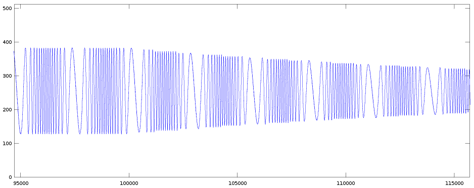

In the full image the envelope of the carrier is clearly visible. Because modulator and carrier use the same rate-settings, the expectation is that the modulator-envelope follows this same pattern. At the very left (only a few pixels wide) we see the damp phase. Followed by the attack phase (until about x=20000). Next the decay phase (until about x=53000). The sustain phase (until about x=100000). And finally the release phase. Let's now zoom in on each of these.
zoom1: Here we clearly see the attack phase of the carrier. The amplitude increases from min to max in about 11 steps. Within each step we also each time see an increase in modulation depth. At the very left we see the damp phase for the carrier. Unfortunately from this experiment, even if we zoom in further, we can't really tell whether the modulator has a similar damp phase or not.
zoom2: Here we see the transition from the attack to the decay phase. We indeed see both the amplitude (carrier) and the modulation depth (modulator) decreasing again in the decay phase.
zoom3: Around x=52000 the decay phase stops and the envelope remains constant in the sustain phase. This is the case for both the modulator and the carrier.
zoom4: This is a very interesting graph. At about x=100000 we switch KEY=OFF, so the release phase starts. The carrier envelope starts to decay, but the modulation depth remains the same!
zoom5: This is another image of the release phase, but now much further to the right. At this point the amplitude (carrier) has almost fallen to zero, but the modulation depth is still exactly the same as in the sustain phase.
So it seems that for the modulator (for EG_TYPE=1) the envelope does not switch to the release phase when KEY goes ON->OFF.
I did a very similar experiment for EG_TYPE=0:
| Operator | AM | PM | EG | KR | ML | KL | TL | WF | FB | AR | DR | SL | RR |
|---|---|---|---|---|---|---|---|---|---|---|---|---|---|
| modulator | 0 | 0 | 0 | 0 | 00 | 0 | 00 | 0 | 0 | 03 | 02 | 01 | 04 |
| carrier | 0 | 0 | 0 | 0 | 08 | 0 | 0 | 03 | 02 | 01 | 04 |

Here KEY switches ON->OFF at around x=80000. The carrier envelope is easy to see. The modulator envelope can be seen in the 'density variation' of the curve. It's clearer if you zoom in, but I haven't included those zoomed images. I hope you trust me when I say that from this and similar experiments I can see that also for EG_TYPE=0 the modulator envelope behaves 'normally' (same as the carrier envelope), except that it also does not go to the (2nd) release phase when we switch KEY=OFF. Instead the envelope keeps decaying at the rate of the 1st release phase.
Side note: this means that the value of mod.RR is not used when mod.EG=1 (it is used when mod.EG=0).
b) Does the modulator-envelope have a damp phase?
[I'm not 100% sure about this sub-section. I'll write it anyway and possible correct it in the future.]
In the subsection above we couldn't conclude anything about the damp phase for the modulator-envelope. Let's try something else. This is the best experiment I could think of right now:
| Operator | AM | PM | EG | KR | ML | KL | TL | WF | FB | AR | DR | SL | RR |
|---|---|---|---|---|---|---|---|---|---|---|---|---|---|
| modulator | 0 | 0 | 0 | 0 | 15 | 0 | 00 | x | 0 | 15 | 00 | 00 | 00 |
| carrier | 0 | 0 | 1 | 0 | 00 | 0 | 0 | 15 | 00 | 00 | 00 |
| reg#0x10 = 0x00 | fnum=0x100 |
| reg#0x30 = 0x00 | max volume / custom instrument |
| reg#0x20 = 0x11 | key-on / block=0 |
I measured for mod.WF=0 and 1
Both modulator and carrier are given the fastest (=immediate) attack rate and the slowest decay/release rates (=take forever). So the only changes in envelope are: - KEY OFF->ON: enter damp phase, during damp phase decay with rate=12 - end-of-damp-phase: envelope immediately jumps to max.
 for mod.WF=0
 for mod.WF=1
Let's first look at the image for mod.WF=1. Between about x=1800..2300 the damp phase is active. But let's first look at the other regions of this graph. Using the half-sine waveform on the modulator is a trick to see (=interleave) the effect of modulator active/inactive on the same graph. Without modulation we see (part of) a sine wave with fairly low frequency. With modulation we see a much higher frequency signal (the difference is so big because mod.ML=15 and car.ML=0). Now look to the region where the damp phase is active and in that region to the subregions where the modulator is active, if you compare those to the non-damp regions the signal is decreasing in frequency. This could be because the modulation depth is decreasing because the modulator envelope is decaying.
In the image for mod.WF=0 I zoomed in deeper on the decay phase (goes from about x=1950..2420 in this image). This also shows a decreasing modulation depth.
Now we can amend the model we obtained in the previous section for the carrier-envelope for the modulator. The only difference seems to be that KEY=OFF does not go to the release phase. The other 4 states (damp, attack, decay, sustain) seem to be the same.
Next steps
There are some TODOs mentioned in this post, and a few more in earlier posts. Most are about details. I could investigate those, but I could also already start reverse engineering the content of the instrument ROM. Not sure yet what I'll do first.
Maybe I should start building a full model (C++ code) for all the things we've learned so far. That would allow to do more numerical comparisons between the model and the measurements. And that might be a useful tool to investigate the items mentioned in the previous paragraph.
<< YM2413 Reverse Engineering Notes 2015-12-24 | YM2413 Reverse Engineering Notes | YM2413 Reverse Engineering Notes 2016-02-10 >>
