|
|
DevelopmentSega Master System / Mark III / Game Gear |
Home - Forums - Games - Scans - Maps - Cheats - Credits |
SMSReader - Connectors
Gluing on the parallel and power connectors
The final step is to glue on the parallel and power connectors. We turn the connectors upside down, so their PCB pins point upwards, then glue the parallel connector at the top left of the board and the power connector at the top right. The actual connector pins in both cases should face backwards. See the photo further down the page for an illustration.
IMPORTANT NOTE - before you glue on the connectors it would be extremely wise to look at the Troubleshooting section and '''solder on the 2 resistors and 2 capacitors mentioned in the solution to problem 1. You are strongly recommended' to fit these components, and it's easiest to do this before'' you glue the connectors on.
Once you've glued them, allow the glue to dry fully (may be up to 24 hours) before continuing with the next step, which is to link the PCB pins to the board.
Wire links - Parallel connector
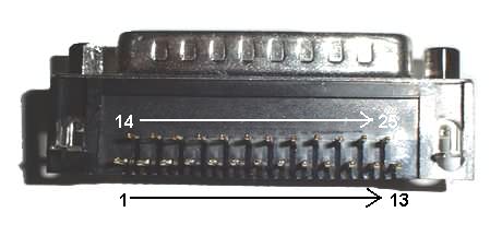
Solder wire links between the following pins and board holes. The photograph above shows the pin numbering for the 25-pin D connector.
- Pin 1 - 8V
- Pin 2 - 6AK
- Pin 3 - 6AF
- Pin 4 - 6AJ
- Pin 5 - 6AI
- Pin 6 - 6AD
- Pin 7 - 6AH
- Pin 8 - 6AE
- Pin 9 - 6AG
- Pin 14 - 8W
- Pin 16 - 4G
- Pin 17 - 3F
- Pin 18 - 6AL
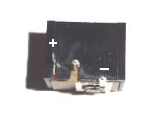
Wire links - Power connector
Connect the Positive (+) pin to 5E, and the Negative (-) pin to 5B.
If you have a connector which differs in appearance from the above, just remember that the outer part of the plug from the power supply is positive, and the centre is negative (ground). Use your multimeter to find the appropriate pins to connect.
Progress so far...
Here's what the SMSReader should look like now ("troubleshooting" capacitors and resistors not shown):

Finished at last!
< Address lines | SMSReader | Testing >
