|
|
DevelopmentSega Master System / Mark III / Game Gear |
Home - Forums - Games - Scans - Maps - Cheats - Credits |
GG Official Docs
- Main manual
- PSG Manual
- Supplementary description for manual
- VDP Manual
Main manual
Precautions for Hardware
1. CPU clock
The CPU clock is 3.579545 MHz.
2. Memory area unusable area
⦾ DFF0H to DFFFH
When a ROM of 1 M or greater is used, the area for bank switching, and so on, is located between FFF0H and FFFH. This area is used for reading (using images) bank data, so do not use it as a normal work area. For this reason, it is necessary to set the stack pointer in such a way that the stack does not use this area.
Example:
⦾ E000H to FFFFH (excluding the area for bank switching, and so on)
This area contains the C000H to 0FFFH RAM image. Do not access an image from this area but from the C000H to DFFFH area instead.
3. VDP initialization
Sometimes, when the power is switched ON, the reset of the CPU is canceled while the VDP remains reset. In order to prevent this, confirm that the value of the V counter in the VDP has become B0H and then access the data.
Example:
IN A,(07EH) ; READ V-COUNTER
CP 0B0H
JP NZ,INIWAIT
RET
4. Interrupt
An interrupt is synchronized with the video timming (at the completion of the effective area or at an arbitrary vertical position).
This interrupt uses the Z80 mode 1 interrupt, hence "IM 1" is executed at the beginning of the program. A return from an interrupt routine is "RET".
System control port
☆ Indicates the state after a power-on reset.
(1) I/O port 00H (Read Only)
| D7 | D6 | D5 | D4 | D3 | D2 | D1 | D0 |
|---|---|---|---|---|---|---|---|
| STT | NJAP | NNTS | * | * | * | * | * |
- STT
- This is an input from the START/PAUSE button.
0: Switch ON
1: Switch OFF - NJAP
- 0: This is the domestic (Japan) mode
1: This is the overseas mode. - NNTS
- 0: This is the NTSC mode.
1: This is the PAL mode.
(2) I/O port 01H (Read/Write)
| D7 | D6 | D5 | D4 | D3 | D2 | D1 | D0 |
|---|---|---|---|---|---|---|---|
| * | PC6 | PC5 | PC4 | PC3 | PC2 | PC1 | PC0 |
This port is used to read/write data when the EXT connector is used as a 7-bit input/output port. (The value after a power-on reset is indeterminate.)
(3) I/O port 02H (Read/Write)
| D7 | D6 | D5 | D4 | D3 | D2 | D1 | D0 |
|---|---|---|---|---|---|---|---|
| NINT | DPC6 | DPC5 | DPC4 | DPC3 | DPC2 | DPC1 | DPC0 |
- DPC6 to DPC0
- 0: PCx becomes the output.
☆ 1: PCx becomes the input. - NINT
- 0: When PC6 is input, an NMI is generated at the fall of PC6.
☆ 1: The above operation is disabled.
- Be sure to set the status of this port to "1". When using this value, first, set the status to "1" after the first NMI is generated, then subsequently set it to "0". If you fail to do this, the next NMI will not be generated.
(4) I/O port 03H (Read/Write)
| D7 | D6 | D5 | D4 | D3 | D2 | D1 | D0 |
|---|---|---|---|---|---|---|---|
| TD7 | TD6 | TD5 | TD4 | TD3 | TD2 | TD1 | TD0 |
- TD7 to TD0
- Used to set the send data during serial communications.
(5) I/O port 04H (Read Only)
| D7 | D6 | D5 | D4 | D3 | D2 | D1 | D0 |
|---|---|---|---|---|---|---|---|
| RD7 | RD6 | RD5 | RD4 | RD3 | RD2 | RD1 | RD0 |
- R07 to RD0
- The receive data is set during serial communications.
(6) I/O port 05H (Read/Write)
Serial communications mode setting
| D7 | D6 | D5 | D4 | D3 | D2 | D1 | D0 |
|---|---|---|---|---|---|---|---|
| BS1 | BS0 | RGN | TON | INT | FRER | RXRO | TXFL |
- TXFL (Read)
- ☆ 0: The next send data is written.
1: The send data cannot be written yet. - RXRD (Read)
- ☆ 0: There is no receive data.
1: There is receive data. - FRER (Read)
- ☆ 0: There is no framing error.
1: There is a framing error. - INT (Read/Write)
- ☆ 0: The following operation is disabled.
1: An NMI is generated when data is received.
* An operation such as that of I/O port 02H is unnecessary. - TON (Read/Write)
- ☆ 0: Sending is disabled.
1: Sending is enabled. (PC4 is forcibly made the output.) - RON (Read/Write)
- ☆ 0: Receive disable.
1: Receive enable. (PCS is forcibly made the input.) - BS1, BS0
- Baud rate setting
| BS1 | BS0 | Baud rate (bps) | |
|---|---|---|---|
| ☆ | 0 | 0 | 4800 |
| 0 | 1 | 2400 | |
| 1 | 0 | 1200 | |
| 1 | 1 | 300 |
(7) I/O port 06H (Write Only)
Left-right distribution of sound
| D7 | D6 | D5 | D4 | D3 | D2 | D1 | D0 |
|---|---|---|---|---|---|---|---|
| NOSL | TN3L | TN2L | TN1L | NOSR | TN3R | TN2R | TN1R |
- TN1R
- 0: The output of TONE 1 to the right is disabled.
☆ 1: The output of TONE 1 to the right is enabled. - TN2R
- 0: The output of TONE 2 to the right is disabled.
☆ 1: The output of TONE 2 to the right is enabled. - TN3R
- 0: The output of TONE 3 to the right is disabled.
☆ 1: The output of TONE 3 to the right is enabled. - NOSR
- 0: The output of NOISE to the right is disabled.
1: The output of NOISE to the right is enabled. - TN1L
- 0: The output of TONE 1 to the left is disabled.
☆ 1: The output of TONE 1 to the left is enabled. - TN2L
- 0: The output of TGNE 2 to the left is disabled.
☆ 1: The output of TONE 2 to the left is enabled. - TN3L
- 0: The output of TONE 3 to the left is disabled
☆ 1: The output of TONE 3 to the left is enabled. - NOSL
- 0: The output of NOISE to the left is disabled.
☆ 1: The output of NOISE to the right is enabled.
(8) Loader access (development board only)
| D7 | D6 | D5 | D4 | D3 | D2 | D1 | D0 | |
|---|---|---|---|---|---|---|---|---|
| LD7 | LD6 | LD5 | LD4 | LD3 | LD2 | LD1 | LD0 | I/O port 30H (Read) |
- LD7 - LD0
- 8-bit data which is read from the printer port
| D7 | D6 | D5 | D4 | D3 | D2 | D1 | D0 | |
|---|---|---|---|---|---|---|---|---|
| 0 | 0 | 0 | 0 | 0 | CLR | BUSY | NSTB | I/O port 31H (Read) |
- NSTB
- STROBE signal input (active Low)
- BUSY
- BUSY signal input (active High)
- CLR
- Loader clear button input (active Low)
When this button is pressed, LD7 to LD0 all become "0", the ACK signal becomes High, and BUSY signal becomes Low.
| D7 | D6 | D5 | D4 | D3 | D2 | D1 | D0 | |
|---|---|---|---|---|---|---|---|---|
| * | * | * | * | * | * | * | ACK | I/O port 30H (Write) |
- ACK
- 0: The ACK signal becomes High.
1: The ACK signal becomes Low (active).
- When the strobe signal falls, eight bits of data are latched, and simultaneously the BUSY signal automatically becomes High. Once the data has been read, the ACK signal is made Low. then High once again. The BUSY signal automatically becomes Low. The LEO lights when the BUSY signal becomes High.
(9) JOYSTICK board (Read Only)
| D7 | D6 | D5 | D4 | D3 | D2 | D1 | D0 | |
|---|---|---|---|---|---|---|---|---|
| DWE | UPE | TR1 | TL1 | RI1 | LEI | DW1 | UP1 | I/O port DCH |
| THE | * | * | * | TRE | TLE | RIE | LEE | I/O port DDH |
- UP1
- 1P UP switch
- DW1
- 1P DOWN switch
- LE1
- 1P LEFT switch
- R11
- 1P RIGHT switch
- TL1
- 1P TRIGGER left button
- TR-1
- 1P TRIGGER right button
- UPE
- EXT UP switch
- DWE
- EXT DOWN switch
- LEE
- EXT LEFT switch
- RIE
- EXT RIGHT switch
- TLE
- EXT TRIGGER left button
- TRE
- EXT TRIGGER right button
- THE
- EXT (Same as PC6 input
One bit is read to port as "1" when either there is nothing connected to the terminal or the corresponding switch is not pressed, and is read as "0" when the switch is pressed.
Material
Using the ROM bank switching and backup RAM
In this model, the capacity of the memory can variy between 1 and 4 Hegabits by bank switching.
Note:
- Area 0
- 0000 to 3FFF
- Area 1
- 4000 to 7FFF
- Area 2
- 8000 to BFFF
The size of one bank is 16 Kbyte. The banks are arranged sequentially in the ROM without overlapping.
A. When the memory capacity is 1 Megabit
Area 0 is fixed to bank 0 (first 16 KBytes of the ROM), and area 1 is fixed to bank 1.
Area 2 enables the banks to be switched over by setting a value in register FFFFH.
| D7 | D6 | D5 | D4 | D3 | D2 | D1 | D0 | |
|---|---|---|---|---|---|---|---|---|
| 0 | 0 | 0 | 0 | 0 | 1/0 | 1/0 | 1/0 | FFFFH |
For bank 0, set 00H (same bank as for area 0).
For bank 7, set 07H.
B. If the capacity is 2 MBytes or more, or a backup RAM is provided
(1) Bank control register (FFFCH)
| D7 | D6 | D5 | D4 | D3 | D2 | D1 | D0 | |
|---|---|---|---|---|---|---|---|---|
| 0/1 | 0 | 0 | 0 | 0/1 | 0 | 1/0 | 1/0 | FFFCH |
| Write protect | Work RAM selection | ROM/external RAM selection | Bank number offset | |||||
- Bank number offset
- All of the banks for areas 0 to 2 area shifted by 1 bank group (8 banks) time the value 1 to 3 is set here. If an offset number causes a bank number to exceed 1FH(31), it goes Bank 0. The value set here will become valid when it is subsequently set in one of bank registers 0 to 2.
- Switching between ROM/external RAM
When 0: The ROM (bank) is assigned to area 2.
When 1: The external RAM is assigned to area 2 (when an external RAM exists).- Work RAM selection
- If 1 is set here, normal access to the work RAM (C000H to DFFFH) of the main body will be prevented. Be sure, therefore, to set 0.
- WRITE PROTECT
- If 1 is set here when the development RAM board is used, data re-write will not take place. Set 0 in mass-production machines.
(2) Bank register 0 (FFFDH)
0000H to 02FFH of area 0 is fixed to bank 0. Bank selection of other areas can be performed by setting a value at FFFDH.
| D7 | D6 | D5 | D4 | D3 | D2 | D1 | D0 | |
|---|---|---|---|---|---|---|---|---|
| 0 | 0 | 0 | 0/1 | 0/1 | 1/0 | 1/0 | 1/0 | FFFDH |
- For bank 00: Set 00H
- For bank 1F: Set 1FH
(3) Bank register 1 (FFFEH)
A Bank selection can.be performed in area 1 by setting a value in FFFEH.
| D7 | D6 | D5 | D4 | D3 | D2 | D1 | D0 | |
|---|---|---|---|---|---|---|---|---|
| 0 | 0 | 0 | 0/1 | 0/1 | 1/0 | 1/0 | 1/0 | FFFEH |
- For bank 00: Set 00H
- For bank 1F: Set 1FH
(4) Bank register 2 (FFFFH)
A bank selection can be performed in area 2 by setting a value in FFFFH.
| D7 | D6 | D5 | D4 | D3 | D2 | D1 | D0 | |
|---|---|---|---|---|---|---|---|---|
| 0 | 0 | 0 | 0/1 | 0/1 | 1/0 | 1/0 | 1/0 | FFFFH |
Caution:
The above registers are not initialized when the power is switched on. For this reason, be sure to initialize them program in 0 to 3FFFH.. (The first 1 KByte is fixed for this purpose.)
Sometimes, the work RAM cannot be accessed normally, hence the work RAM (and also sub-routines, ) are allowed to be used after this initialization. When using a backup RAM, do not use the first and last addresses because there is a possibility of the data being changed when the power is switched on.
Example
DI
IM 1
LD SP,0DFF0H
LD A,000H
LD (0FFFCH),A
LD A,000H
LD (0FFFDH),A
LD A,001H
LD (0FFFEH),A
LD A,002H
LD (0FFFFH),A
// ...
MEMORY MAPPING
MEMORY MAP
0000 ┌───────────────────────────┐
     │Cartridge                  |
     |                           |
     |Area 0                     |
4000 |┄┄┄┄┄┄┄┄┄┄┄┄┄┄┄┄┄┄┄┄┄┄┄┄┄┄┄|
     |Cartridge                  |
     |                           |
     |Area 1                     |
8000 |┄┄┄┄┄┄┄┄┄┄┄┄┄┄┄┄┄┄┄┄┄┄┄┄┄┄┄|
     |Cartridge                  |
     |                           |
     |Area 2                     |
C000 |┄┄┄┄┄┄┄┄┄┄┄┄┄┄┄┄┄┄┄┄┄┄┄┄┄┄┄|
     |8 Kbyte work RAM           |
     |                           |
E000 |┄┄┄┄┄┄┄┄┄┄┄┄┄┄┄┄┄┄┄┄┄┄┄┄┄┄┄|
     |Top image                  |
     |                           |
FFFF └───────────────────────────┘
I/O MAP
00 ┌───────────────────────────┐
   │00,01,02,03,04,05 and 06   |
   |: Used with system control.|
   |                           |
40 |┄┄┄┄┄┄┄┄┄┄┄┄┄┄┄┄┄┄┄┄┄┄┄┄┄┄┄|
   |7E -- Read                 |
   |      : V counter          |
   |7F -- Read                 |
   |      : H counter          |
   |7F -- Write                |
   |      : PSG                |
   |                           |
80 |┄┄┄┄┄┄┄┄┄┄┄┄┄┄┄┄┄┄┄┄┄┄┄┄┄┄┄|
   |BE and BF                  |
   |: Used with VDP            |
   |                           |
C0 |┄┄┄┄┄┄┄┄┄┄┄┄┄┄┄┄┄┄┄┄┄┄┄┄┄┄┄|
   |DC and DD                  |
   |: Used as JOYSTICK inputs. |
   |                           |
FF └───────────────────────────┘
Never access data using an image address.
PSG Manual
The PSG (Programmable Sound Generator) contains three tone generators and one noise generator. Each of the tone and noise generators can be distributed left and right, enabling a pseudo stereo effect to be generated. (See "System Control Port".)
Control of the PSG itself, which is described below, is performed by means of the write operation to I/O area 7FH.
The basic clock is 3.579545 MHz. The data to be sent from the CPU is immediately latched in the PSG, hence there is no need for a wait. The sound output goes OFF in the case of a power-on reset. Design the software so that the output goes OFF at the beginning of the program as well.
[1] Tone generator
Each tone generator consists of a frequency setting section (programmable counter) and a level setting section (programmable attenuator).
(1) Method of calculating the 10-bit frequency division ratio n
At the frequency setting section, the basic clock is frequency-divided to 1/32. This is further frequency divided by the tone counter set by the 10 bits F9 (MSB: top bit) to F0 (LSB: bottom bit).
Consequently, the basic clock frequency is divided by 32, then the desired frequency can be output by setting the value obtained by dividing the frequency-divided clock by the desired frequency in F9 to F0.
n = N/(32 x f)
Where:
- n = 10-bit frequency division ratio (F9 to F0)
- N = Basic clock
- f = Desired frequency
(2) Tone frequency setting
Set the 10-bit frequency division ratio (F9 to F0) in the tone counter in order to obtain the desired frequency. The 1st and 2nd bytes are identified by means of the top bit.
| 1st byte | 2nd byte | ||||||||||||||
| D7 | D6 | D5 | D4 | D3 | D2 | D1 | D0 | D7 | D6 | D5 | D4 | D3 | D2 | D1 | D0 |
|---|---|---|---|---|---|---|---|---|---|---|---|---|---|---|---|
| * | REG. ADDR. | n | * | n | |||||||||||
| 1 | R2 | R1 | R0 | F3 | F2 | F1 | F0 | 0 | x | F9 | F8 | F7 | F6 | F5 | F4 |
| R2 | R1 | R0 | Control register allocation | 1st |
|---|---|---|---|---|
| 0 | 0 | 0 | Tone generator 1 | 8x |
| 0 | 1 | 0 | Tone generator 2 | Ax |
| 1 | 0 | 0 | Tone generator 3 | Cx |

Frequency division ratio with respect to the output frequency
(3) Example of frequency setting
Consider an example in which the basic clock frequency is 3.579545 MHz and the desired frequency of 440 Hz is output from TONE 1. (corresponding to "A" on the musical scale)
a. Calculation of frequency division ratio n
n = N/(32 x f)
  = 3579545/(32 x 440)
  = 254.229
n is a 10-bit integer, hence the nearest integral value is 254.
Consequently, the frequency actually output is
f = N/(32 x n)
  = 3579545/(32 x 254)
  = 440.397 (Hz)
Here, the pitch error ΔC is obtained according to the following equation.
ΔC = {(f' - f)/f}/(['1280']√2-1)
   = {(440.397-440)/440}/(['1280']√2-1)
   = (0.397/440)/0.000578 = 1.56
b. Oata sent to PSG
n = 254 = 0011111110B
| 1st byte | 2nd byte | ||||||||||||||
| * | REG. ADDR. | n | * | n | |||||||||||
| 1 | R2 | R1 | R0 | F3 | F2 | F1 | F0 | 0 | x | F9 | F8 | F7 | F6 | F5 | F4 |
| D7 | D6 | D5 | D4 | D3 | D2 | D1 | D0 | D7 | D6 | D5 | D4 | D3 | D2 | D1 | D0 |
|---|---|---|---|---|---|---|---|---|---|---|---|---|---|---|---|
| 1 | 0 | 0 | 0 | 1 | 1 | 1 | 0 | 0 | x | 0 | 0 | 1 | 1 | 1 | 1 |
(4) Tone level setting
The frequency set by the tone generator is sent to the level setting section where the volume level is set. The level setting section is a programmable attenuator which enables the volume leve to be set in 16 steps from 0 d8 to OFF according to a 4-bit attenuation value.
1st byte only
| D7 | D6 | D5 | D4 | D3 | D2 | D1 | D0 |
|---|---|---|---|---|---|---|---|
| * | REG. ADDR. | ATT. DATA | |||||
| 1 | R2 | R1 | R0 | A3 | A2 | A1 | A0 |
| R2 | R1 | R0 | Control register allocation | HEX |
|---|---|---|---|---|
| 0 | 0 | 1 | Tone 1 attenuation | 9x |
| 0 | 1 | 1 | Tone 2 attenuation | Bx |
| 1 | 0 | 1 | Tone 3 attenuation | Dx |
Attenuation
| (db) | A3 A2 A1 A0 | HEX |
|---|---|---|
| 0 | 0 0 0 0 | x0 |
| 2 | 0 0 0 1 | x1 |
| 4 | 0 0 1 0 | x2 |
| 6 | 0 0 1 1 | x3 |
| 8 | 0 1 0 0 | x4 |
| 10 | 0 1 0 1 | x5 |
| 12 | 0 1 1 0 | x6 |
| 14 | 0 1 1 1 | x7 |
| 16 | 1 0 0 0 | x8 |
| 18 | 1 0 0 1 | x9 |
| 20 | 1 0 1 0 | xA |
| 22 | 1 0 1 1 | xB |
| 24 | 1 1 0 0 | xC |
| 26 | 1 1 0 1 | xD |
| 28 | 1 1 1 0 | xE |
| OFF | 1 1 1 1 | xF |
[2] Noise generator
The noise generator consists of a noise generator circuit and a level setting section. The source of the noise supplied from the noise generator circuit is a shift register with EX-OR feedback. Each time the noise control register changes, the shift register is cleared.
The shift clock of this shift register is determined by four modes that are in turn determined by NF0 and NF1. If NF0 = NF1 = 0, for example, the shift clock becomes (N/32)/16. In this case, if FB = 0, this shift clock will be frequency-divided by 16, resulting in synchronous noise of a frequency of N/(32 x 16 x 16). If FB = 1, the shift register will be driven by this shift clock with EX-OR feedback, resulting in the generation of white noise.
(1) Noise generator circuit control
1st byte only
| D7 | D6 | D5 | D4 | D3 | D2 | D1 | D0 |
|---|---|---|---|---|---|---|---|
| * | REG. ADDR. | SHIFT | |||||
| 1 | 1 | 1 | 0 | x | FB | NF1 | NF0 |
| FB | Noise Generation |
|---|---|
| 0 | Synchronous Noise |
| 1 | White noise |
| NF1 | NF0 | Shift clock | k |
|---|---|---|---|
| 0 | 0 | (N/32)/k | 16 |
| 0 | 1 | (N/32)/k | 32 |
| 1 | 0 | (N/32)/k | 64 |
| 1 | 1 | Tone generator 3 | At this time, the tone of the noise can be varied continuously |
a. Synchronous noise (FB = 0)
When 0NF0 = NF1 = Value other than 1
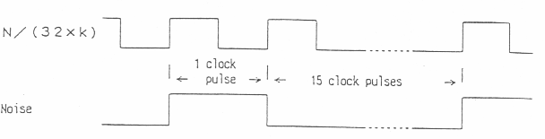
- The noise frequency is (N/(32 x k))/16 = N/(32 x k x 16)
When NFO = NF1 = 1 (Control by tone 3)
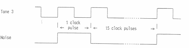
- The noise frequency is (frequency TONE 3)/16 = N/(32 x n x 16)
b.White Noise (FB = 1)
Spectrum when NF0 = 0 NF1 = 1 n=1

(2) Noise level setting
1st byte only
| D7 | D6 | D5 | D4 | D3 | D2 | D1 | D0 |
|---|---|---|---|---|---|---|---|
| * | REG. ADDR. | ATT. DATA | |||||
| 1 | 1 | 1 | 1 | A3 | A2 | A1 | A0 |
- The attenuation control is the same as for "Tone".
[3] Register address feed
PSG uses the three bits R2 to RO of the 1st byte to judge which control register the data has been sent from.
| R2 | R1 | R0 | Control register allocation | 1st |
|---|---|---|---|---|
| 0 | 0 | 0 | Tone 1 frequency division ratio | 8x |
| 0 | 0 | 1 | Tone 1 attenuation | 9x |
| 0 | 1 | 0 | Tone 2 frequency division ratio | Ax |
| 0 | 1 | 1 | Tone 2 attenuation | Bx |
| 1 | 0 | 0 | Tone 3 frequency division ratio | Cx |
| 1 | 0 | 1 | Tone 3 attenuation | Dx |
| 1 | 1 | 0 | Noise generator circuit control | Ex |
| 1 | 1 | 1 | noise attenuation | Fx |
[4] Correlation between the sound elements and PSG
| Sound element | Physical element | Correlation with PSG |
|---|---|---|
| Pitch of sound | Frequency | [1] - (2) Tone frequency setting, [2]` - (1) Noise generator circuit control |
| Tone | Hermonic components | This is mainly related to wave length. In the tone generation mode, the PSG can output three frequencies simultaneously from only a 50% duty pulse waveform. Consequently, by combining attenuation control with this mode, the harmonic components can be controlled. In the synchronous noise mode, a 6.25% duty pulse waveform. |
| Strength of tone | Amplitude | As described in [1] - (3) and [2]` - (2), the attenuation of the three tones and noise can be controlled by 4-bit data. |
| Way in which sound is emitted. | Envelope  | The wave length at left can be realized by using external data to control each attenuation. This can be done in the range where the 4-bit attenuation data is rewritten and envelope sequence control performed at each step. The tone and noise frequencies can be controlled by the range in which component control can be performed. |
Relation between musical interval and frequency division ratio for scale divided equally into 12 parts (basic clock: 3.579545 MHz)
| Musical interva1 | Frequency division ratio | HEX | PSG output [Hz] | Actual frequency [Hz] |
|---|---|---|---|---|
| A 2 | 1017 | X9 3F | 109.991 | 110.000 |
| A♯2 | S60 | X0 3C | 116.522 | 116.541 |
| B 2 | 906 | XA 38 | 123.467 | 123.471 |
| C 3 | 855 | X7 35 | 130.832 | 130.813 |
| C♯3 | 807 | X7 32 | 138.613 | 138.591 |
| D 3 | 762 | XA 2F | 146.799 | 146.832 |
| D♯3 | 719 | XF 2C | 155.578 | 155.563 |
| E 3 | 679 | X7 2A | 164.744 | 164.814 |
| F 3 | 641 | X1 28 | 174.510 | 174.614 |
| F♯3 | 605 | X0 25 | 134.894 | 184.997 |
| G 3 | 571 | XB 23 | 195.904 | 195.998 |
| G♯3 | 539 | XB 21 | 207.534 | 207.652 |
| A 3 | 508 | XC 1F | 220.199 | 220.000 |
| A♯3 | 480 | X0 1E | 233.044 | 233.082 |
| B 3 | 453 | X5 1C | 246.934 | 246.942 |
| C 4 | 428 | XC 1A | 261.357 | 261.626 |
| C♯4 | 404 | XA 19 | 276.884 | 277.183 |
| D 4 | 381 | XD 17 | 293.598 | 293.665 |
| D♯4 | 360 | X8 16 | 310.725 | 311.127 |
| E 4 | 339 | X3 15 | 329.973 | 329.628 |
| F 4 | 320 | X0 1A | 349.565 | 349.228 |
| F♯4 | 302 | XE 12 | 370.400 | 369.994 |
| G 4 | 285 | XD 11 | 392.495 | 391.995 |
| G♯4 | 269 | XD 10 | 415.840 | 415.305 |
| A 4 | 254 | XE 0F | 440.397 | 440.000 |
| A♯4 | 240 | X0 0F | 466.087 | 466.164 |
| B 4 | 226 | X2 0E | 494.960 | 493.883 |
| C 5 | 214 | X6 00 | 522.715 | 523.251 |
| C♯5 | 202 | XA 0C | 553.767 | 554.365 |
| D 5 | 190 | XE 0B | 588.742 | 587.330 |
| D♯5 | 180 | X4 0B | 621.450 | 622.254 |
| E 5 | 170 | XA 0A | 658.005 | 659.255 |
| F 5 | 160 | X0 0A | 699.131 | 698.456 |
| F♯5 | 151 | X7 09 | 740.801 | 739.989 |
| G 5 | 143 | XF 08 | 782.244 | 763.991 |
| G♯5 | 135 | X7 08 | 828.600 | 830.609 |
| A 5 | 127 | XF 07 | 880.795 | 880.000 |
| A♯5 | 120 | X8 07 | 932.174 | 932.328 |
| B 5 | 113 | X1 07 | 989.920 | 987.767 |
| C 6 | 107 | XB 06 | 1045.429 | 1046.502 |
| C♯6 | 101 | X5 06 | 1107.534 | 1108.731 |
| D 6 | 95 | XF 05 | 1177.484 | 1174.659 |
| D♯6 | 90 | XA 05 | 1242.899 | 1244.508 |
| E 6 | 85 | X5 05 | 1316.011 | 1318.510 |
| F 6 | 80 | X0 05 | 1398.262 | 1396.913 |
| F♯6 | 76 | XC 0A | 1471.654 | 1479.978 |
| G 6 | 71 | X7 0A | 1575.506 | 1567.982 |
| G♯6 | 67 | X3 0A | 1669.566 | 1661.219 |
| A 6 | 64 | X0 0A | 1747.827 | 1760.000 |
| A♯6 | 60 | XC 03 | 1864.349 | 1864.655 |
| B 6 | 57 | X9 03 | 1962.473 | 1975.533 |
- f = 3579545/(32 x n) n: 10-bit frequency division Maximum frequency is n = 1
- In the previous table, musical interval was calculated on the basis of 440 Hz as concert pitch.
- Regarding HEX. the X part is as follows:
- Tone 1 → 8
- Tone 2 → A
- Tone 3 → C
1st is the 1st byte 2nd is the 2nd byte
The upper limit is 3579545/32-1

If a frequency of no greater than that generated by the tone generator is output, the outputs shown in the table below will be obtained due to the synchronous noise mode of the noise generator section. (Basic clock: 3.579545 MHz)
| Musical interval | Frequency division ratio | HEX (TONE3) | PSG output [Hz] | Actual frequency [Hz] |
|---|---|---|---|---|
| C 0 | 428 | CC 1A | 16.335 | 16.352 |
| C♯0 | 404 | C4 19 | 17.305 | 17.324 |
| D 0 | 381 | C0 17 | 18.350 | 13.354 |
| D♯0 | 360 | C8 16 | 19.420 | 19.445 |
| E 0 | 339 | C3 15 | 20.623 | 20.602 |
| F 0 | 320 | C0 14 | 21.848 | 21.827 |
| F♯0 | 302 | CE 12 | 23.150 | 23.125 |
| G 0 | 285 | CD 11 | 24.531 | 24.500 |
| G♯0 | 269 | CD 10 | 25.990 | 25.957 |
| A 0 | 254 | CE 0F | 27.525 | 27.500 |
| A♯0 | 240 | C0 0F | 29.130 | 29.135 |
| B 0 | 226 | C2 0E | 30.935 | 30.868 |
| C 1 | 214 | C6 0D | 32.670 | 32.703 |
| C♯1 | 202 | CA 0C | 34.610 | 34.648 |
| D 1 | 190 | CE 0B | 36.796 | 36.708 |
| D♯1 | 180 | C4 0B | 38.841 | 38.891 |
| E 1 | 170 | CA 0A | 41.125 | 41.203 |
| F 1 | 160 | C0 0A | 43.696 | 43.654 |
| F♯1 | 151 | C7 09 | 46.300 | 46.249 |
| G 1 | 143 | CF 08 | 48.890 | 48.999 |
| G♯1 | 135 | C7 08 | 51.787 | 51.913 |
| A 1 | 127 | CF 07 | 55.050 | 55.000 |
| A♯1 | 120 | C8 07 | 58.261 | 58.270 |
| B 1 | 113 | C1 07 | 61.870 | 61.735 |
| C 2 | 107 | CB 06 | 65.339 | 65.406 |
| C♯2 | 101 | C5 06 | 69.221 | 69.296 |
| D 2 | 95 | CF 05 | 73.593 | 73.416 |
| D♯2 | 90 | CA 05 | 77.681 | 77.782 |
| E 2 | 85 | C5 05 | 82.251 | 82.407 |
| F 2 | 80 | C0 05 | 87.391 | 87.307 |
| Fv2 | 76 | CC 04 | 91.991 | 92.499 |
| G 2 | 71 | C7 04 | 98.469 | 97.999 |
| G♯2 | 67 | C3 04 | 104.348 | 103.826 |
- Set E3H for control of the noise generator circuit (synchronous noise mode). f = T0NE 3 frequency/16 = 3579545/(32 x n x!6)
Supplementary description for manual
A. System control port
(3) I/O port 02H (Read/Write)
- Normally, be sure to make the status of this port "1". When using this value, first, set the status to "1" after the first NMI is generated, then subsequently set it to "0". If you fail to do this, the next NMI will not be generated.
Addition:
An NMI is enabled after the execution of one command from when the port is set to "0". This is to prevent the hMI from becoming active once again in the NMI routine. Normally, therefore, perform the following processing.
...
LD A,11XXXXXXB
OUT (002H),A
LD A,01XXXXXXB
OUT (002H),A
R£TN ; An hMI is enabled after this command.
B. System control port
(6) I/O port 05H (Read/Write)
Mode setting for serial communications
- INT
- There is no need to perform an operation such as that of I/O port 02H.
Addition
When using this function (serial communications NMI), set NINT of I/O port 02H to the disable state ("1"). An NMI will be generated at the fall of the pulse at the NMI terminal. If, however, a serial communications NMI is generated, the NMI terminal will go LOW, preventing the next NMI from becoming active. The NMI terminal is made HIGH as a result of reading the data of I/O port 04H, so read the data each time an NMI is generated. If it is conceivable that the NMI terminal may already be LOW at the start of the communications, perform a "dummy" read operation once.
(7) I/O port 06H (Write Only)
Left-right distribution of sound
Supplementary explanation
When the headphones are plugged in, the output from the speaker is cut off and instead the sound will be heard in stereo from the headphones. When the earphones are not plugged in, the sound will be heard from the speaker in monaural. In the latter case, the distribution of the sound from all channels (three tones 4 noise) will be enabled. If the output from the left and right channels was disabled not by attenuator control but by distribution, the sound will not be heard from the headphones but will.be.heard from the speaker. To turn off both the left and right channels of the speaker, use the PSG.
C. Communications
(1) Connecting the communications cable
Cross-connect the game gear communications cable as shown below.
Communications connector
| 1 | PC0 | To opposite side PC2 |
| 2 | PC1 | To opposite side PC3 |
| 3 | PC2 | To opposite side PC0 |
| 4 | PC3 | To opposite side PCI |
| 5 | +5V | |
| 6 | PC4 | To opposite side PCS |
| 7 | PC6 | To opposite side PC8 |
| 8 | GND | To opposite side GND |
| 9 | PC5 | To opposite side PC4 |
| 10 | NC |
(2) Parallel communications
PC0 to PCS can be set to an arbitrary input or output by means of the control register of the I/O port. 8e sure to set the connecting terminals so that the terminal on one side is the output, and that on the opposite side is the input. (Never make the terminals on both sides the output.) In the case of parallel communications, control the exchange of data either by polling using software (check the data), or by applying an interrupt (NMI) using PC6. When applying an NMI using PC6, however, it is necessary to take noise into account because an NMI will be generated by a momentary change in PC6.
(3) Serial communications
Serial communications can be performed in one of two single directions, from PC4 (output from one’s own side) → PCS (input to opposite side), or from PC5 (input to one’s own side) <- PC4 (output from opposite side). Serial and parallel conversion and interrupt (WI) generation (when data is received) accompanying the receiving or sending of data take place automatically when the hardware is connected to these terminals. To perform serial communications, set TON and RON of I/O port OSH to "1". By doing this. PC4 will automatically become the output, and PC5 the input. These settings will take priority over the PC4 and PC5 input/output settings. 8its other than those of PC4 and PC5 will become the settings of I/O port 02H. (Like (2). never make both terminals the output.) When performing serial communications only, be sure to set NINT of I/O port 02H to prevent PC6 from generating an NMI.
(4) Coexistence of parallel and serial communications
When performing serial communications, PC4 and PCS are used to send and receive serial data. Parallel communications can be performed using the bits other than these. An NMI can be generated by PCS and also by receiving of serial data. In the former case, care must be taken because PC6 goes not have a data receiving flag such as the serial RXR0. The blocks of the circuit used to generate these NMI are shown below.

An NMI is generated when one of the two reset flip-flops is set. (This is because an NMI is generated not when the pulse level is LOW but when the pulse falls.) It should be appreciated that it is necessary to reset the set flip-flop so that the next NMI can be generated.
VDP Manual
(1) GAME GEAR FEATURES
- 16-kbyte VRAM
- Scroll SCREEN: Horizontal 20 cells x vertical 18 cells (one cell = 8x8 dots)
The virtual area is 32 cells in the horizontal direction x 28 cells in the vertical direction, permitting smooth scrolling in the horizontal and vertical directions. - The scroll screen can be left-right reversed, and up-down reversed, and also its priority with respect to sprites can be selected.
- 64 colors out of a total of 4096 colors can be displayed for each dot of the scroll surface. By designating a palette for each cell, two kinds of 16-color groups can be selected.
- Sixteen sprites (aovable objects) can be displayed on a single screen. Up to eight sprites of either 8x8 dots or 8 x 16 dots (vertical) in size can be selected on the same horizontal line.
- Sixteen colors out of a total of 4096 can be displayed for each dot of a sprite.
- The maximum number of character pattern definitions (8x3 dots) is 448 for both the scroll sur face and sprites (256 of these are used for sprites, however this is reduced to 128 for 8 x 16 sprites).
(2) Effective area and CO display area
This VDP was initially designed on the basis of a TV (NTSC) format, hence only a portion of the picture created by the VDP is displayed on the LCD. This relationship is shown in the figure below.

Consequently, when a developing board or TV adapter is installed, the LCO display part will appear on part of the screen, and the backdrop color will be displayed on the remaining part. (Set to a color approaching that of a game screen.) When the screen is ON and timing is in the effective area, the VDP will generate an image, hence (even for a part which is not displayed on the LCD) if timing is within this area, the game program will be subjected to various restrictions (wait condition, etc.).
(3) Image display
Note: In the following description, there are bits that are fixed at "0" or "1" and should remain in this default position.
(1) Access to VDP
It is necessary to set data in the VDP register, color RAM, VRAM, and so on in order to display an image on the screen. This is because data cannot be accessed directly from the CPU, and must be accessed instead via the VDP assigned to the I/O port.
a. Reading the status register
The status register indicates various states of the VDP. It can read the CPU by reading the I/O port BFH. This register can read the CPU at any time without any need to take account of the VDP delay.
| D7 | D6 | D5 | D4 | D3 | D2 | D1 | D0 | |
|---|---|---|---|---|---|---|---|---|
| F | 9S | C | Meaningless | I/O port BFH | ||||
Interrupt flag (F)
This flag is "1" when the effective area is completed. If, at this time, the IE bit of the VDP register #1 is set to "1", the interrupt line from the VDP to the CPU will become Low, causing an interrupt to be applied (generally called a V interrupt). If the program leaves the interrupt routine in this state, the interrupt will be applied again immediately (an interrupt of Z80 will not occur at the edge of plus, hence the status register will be read at the beginning of the interrupt routine and the flag will be reset.
Example
PUSH AF
IN A,(08FH) ; RESET STATUS FLAG
...
POP AF
EI
RET
- This flag is not set in the case of an interrupt (normally called an H interrupt) at an arbitrary vertical position, hence by checking this flag it is possible to identify two kinds of interrupts. A Z80 interrupt uses mode 1, hence "IM 1" is implemented.
9th sprite (9S)
If the 9th and higher sprites exist on the same horizontal line (in the effective area), and the interrupt flag (F) is "O", the 9S bit will be set to "1". (within the effective area)
Collision flag
This flag is set t0 "1" if dots of color codes other than 0, of two or more sprites collide (coincide). --In the effective area
- The above flags are reset by a power-on reset and a status register read-out, and are renewed each frame. Once a flag is set, it will not be reset again apart from a power-on reset, so long as the status register is not read. For example, if sprites overlap each other, the collision flag will be set, however if the status register is not read, the flag will remain set even if the sprites subsequently separate from each other.
b. Writing to VDP registers (#0 to #10)
A selection of the display mode or other functions and also data for each base address setting are written to the VDP registers (write-only registers). Data transfer from the CPU takes place in the following format. Data can be written to these registers without any need to take account of VDP delay.
| b7 | b6 | b5 | b4 | b3 | b2 | b1 | b0 | |
|---|---|---|---|---|---|---|---|---|
| First byte: Data set in the register (I/O port BFH) | D7 | D6 | D5 | D4 | D3 | D2 | D1 | D0 |
| Second byte: Register selection (I/O port BFH) | 1 | 0 | 0 | 0 | R3 | R2 | R1 | R0 |
To set data in a VDP register, the data is inputted in the first byte. The second byte is used to indicate the register where the data is to be transferred.
The bottom four bits (R3 to R0) of the second byte designate the data transfer destination registers (#O to #10). b7 must be "1" and b6 to b4 must be "0". Never attempt to access registers that do not exist (#11 to #15).
Example: When setting E0H in register #1
LD A,0E0H
OUT (0BFH),A ; OATA
LD A,081H
OUT (0BFH),A ; REGISTER NO.
- The logic inside the VDP determines whether data sent to the VDP is the first byte or the second byte. This internal logic is set to receive the first byte in the following cases.
- After a power-on reset
- After the status register has been read
- After the second byte has been written
- I/O port BEH write or read (VRAM or color RAM access)
Consequently, if data is written in the correct sequence, [IN A, (OBFH)] in the previous example can be omitted. Here, it is necessary to takes steps to prevent the CPU from accepting an interrupt while data is being written to a register or VRAM address setting is being carried out (described later). If an interrupt is applied after the first byte has been sent, the data will fail to be transferred correctly if the status register is read during the interrupt (the second byte written after the program leaves the interrupt routine will be received as the first byte.
[Page 5 missing]
d. Reading from VRAM
The CPU reads data from the VRAM via the VDP. The addresses are auto-incremented. (See sub-section "Writing to VRAM".)
| b7 | b6 | b5 | b4 | b3 | b2 | b1 | b0 | |
|---|---|---|---|---|---|---|---|---|
| First byte: Address set-up (I/O port BFH) | A7 | A6 | A5 | A4 | A3 | A2 | A1 | A0 |
| Second byte: Address set-up (I/O port BFH) | 0 | 0 | A13 | A12 | A11 | A10 | A9 | A8 |
| Third byte: Write data (I/O port BEH) Necessary number of repetitions | D7 | D6 | D5 | D4 | D3 | D2 | D1 | D0 |
The bottom eight bits of the VRAM address are set up by the first byte.
The top six bits are set up by the second byte. Be sure to set b7 and b6 to "0".
The data is read by the third byte.
Once the address register has been set up, the data will be incremented automatically each time the third byte data is transferred.
- A delay time is necessary for the CPU to read data from the VRAM. A wait of at least 28 clock pulses is necessary during the first third-byte transfer after the completion of address setting prior to a read operation (this is slightly different to the case of a write operation to the VRAM).
- Insert the same wait for reading the subsequent third bytes. This applies only to cases where the VDP displays a picture (effective area). In the following two cases, there is no need for any wait whatever. (This is the same as for a write operation to the VRAM.)
- When the blank bits of the VDP register #1 are set to "0" and the screens is turned OFF.
- During the interval of 4.3 m from when an interrupt occurs upon completion of the effective area until the commencement of the next effective area.
Example: Write two addresses continuously from VRAM address 0000H. (effective area & screen ON)
OUT (0BFH),A
LD A,000H
OUT (0BFH),A
PUSH IX ; WAIT 15 CLOCK
POP IX ; WAIT 14 CLOCK TOTAL 29 CLOCK
IN A,(0BEH)
PUSH IX ; WAIT
POP IX ; WAIT
IN A,(0BEH)
PUSH IX ; WAIT
POP IX ; WAIT
e. VRAM special access
If data is written to a VRAM using address auto increment, it will be written to a continuous address. Data can be written to discrete addresses by dummy reading it. Observe the wait conditions while a screen is being displayed in the effective area.
Example: Write 256 bytes 01H to each address from VRAM address 3800H. (effective area & screen ON)
OUT (0BFH),A
LD A,078H
OUT (0BFH),A
LD B,000H
LOOP:
LD A,001H ; 7 CLOCK TOTAL 41 CLOCK
OUT (0BEH),A ; 11 CLOCK
PUSH IX ; WAIT 15 CLOCK
POP IX ; WAIT 14 CLOCK TOTAL 29 CLOCK
IN A,(0BE1)
PUSH AF ; 11 CLOCK
POP AF ; 10 CLOCK
DJNZ LOOP ; 13 CLOCK
- Do not perform irregular access to VRAM (e.g. setting read addresses and writing data to them, or vice-versa). Also, do not use the above method to write data to a color RAM.
f. Writing to the color RAM
The VDP contains a 12-bit x 32-word color RAM. This color RAM is a write-only RAM. The CPU transfers data to the color RAM via the VDP, using an auto increment address register.
| b7 | b6 | b5 | b4 | b3 | b2 | b1 | b0 | ||
|---|---|---|---|---|---|---|---|---|---|
| First byte: Address set-up (I/O port BFH) | 0 | 0 | A5 | A4 | A3 | A2 | A1 | A0 | |
| Second byte: 0C0H set-up (I/O port BFH) | 1 | 1 | 0 | 0 | 0 | 0 | 0 | 0 | |
| Third byte: Write data (I/O port BEH) Repetition of write necessary number of times | (For even addresses) | G3 | G2 | G1 | G0 | R3 | R2 | R1 | R0 |
| (For odd addresses) | 0 | 0 | 0 | 0 | B3 | B2 | B1 | B0 | |
The first byte sets up five bits of the color RAM address.
The second byte always sets COH.
The third byte transfers data.
Once the address register is set up, it is automatically incremented each time the third byte of data is transferred. The color RAM has two addresses (even and odd addresses) which comprise a single color (12 bits). Normally, therefore, the even address is set up, then the R & G data and B data are set in that sequence. Actual writing of data to the color RAM takes place when data is set in the odd address (12 bits of data are written). Note, however, that when the odd address is set up and B data written, the R & G data previously set will be written.
- The delay time conditions when the CPU writes data to the color RAM are exactly the same as those for writing data to the VRAM.
Example :
Write 0FH & 00H (bright red) and F0H & 00H (bright green) from color RAM address 04H. (effective area & screen ON)
OUT (0BFH),A
LD A,0C0H
OUT (0BFH),A
LD A,00FH
OUT (0BEH),A
PUSH AF ; WAIT 11 CLOCK
POP AF ; WAIT 10 CLOCK
LD A,000H ; 7 CLOCK TOTAL 28 CLOCK
OUT (0BEH),A
PUSH AF ; WAIT
POP AF ; WAIT
LD A,0F0H
OUT (0BEH),A
PUSH AF ; WAIT
POP AF ; WAIT
LD A,000H
OUT (0BEH),A
PUSH IX ; WAIT 15 CLOCK
POP IX ; WAIT 14 CLOCK TOTAL 29 CLOCK
- If data is written to the color RAM when a TV scan is on the screen (including the border),
the screen will flicker. This cannot be avoided even by setting the BLANK bit to "0" to turn the screen OFF. For this reason, write data to the color RAM during V blanking.
(2) VDP register (write only)
a. Register #0, register #1
(These two registers are reset to "0" at power switch-on.)
| D7 | D6 | D5 | D4 | D3 | D2 | D1 | D0 | |
|---|---|---|---|---|---|---|---|---|
| Register #0 | HVS | 0 | 0 | IE1 | EC | 1 | 1 | 0 |
| Register #1 | 1 | BLANK | IE | 0 | 0 | 0 | SIZE | 0 |
- EC (Early Clock)
- 0: Normal
1: The horizontal position of all sprites shifts eight dots to the left. - IE, IE1 (Interrupt Enable)
- IE is an interrupt enable bit used at the completion of the effective area.
0: Disable
1: Enable
IE1 is an interrupt enable bit used at an arbitrary vertical position.
0: Disable
1: Enable
- HVS
- 0: Normal
1: The two cells at the right end of the LCD screen are not scrolled in the vertical direction.\\ * A horizontal scroll is not disabled. - SIZE
- 0: Normal
1: The sprite size becomes 8 x 16 dots. In this case, the top seven bits of the character No. are enabled (number of definitions = 128 kinds). - BLANK
- 0: Nothing is displayed on the screen. In this case, the backdrop color is displayed, and the wait used for VDP access is unnecessary.
1: An image is displayed on the screen.
* The screen display can be turned ON and OFF at any time.
b. Register #2
(This register is not reset at power switch-on, hence its contents are indeterminate.)
This register determines the base address (starting address) of the pattern name table in the VRAM. The pattern name table requires 32 cells (horizontal) x 28 cells (vertical) x 2 bytes = 1792 (700H) bytes. The relation between the set data and the base address is shewn below.
| D7 | D6 | D5 | D4 | D3 | D2 | D1 | D0 | ||||||||||
| 1 | 1 | 1 | 1 | X | X | X | 1 | Register #2 | |||||||||
| ↓ | ↓ | ↓ | |||||||||||||||
| Base address | X | X | X | 0 | 0 | 0 | 0 | 0 | 0 | 0 | 0 | 0 | 0 | 0 | |||
| A13 | A12 | A11 | A10 | A9 | A8 | A7 | A6 | A5 | A4 | A3 | A2 | A1 | A0 | ||||
((Data)- F1H) x 400H = Base address
| Set data | Base address |
|---|---|
| F1H | 0000H |
| F3H | 0800H |
| F5H | 1000H |
| F7H | 1800H |
| F9H | 2000H |
| FBH | 2800H |
| FDH | 3000H |
| FFH | 3800H |
Normally FFH is set and the pattern name table started from 3800H.
c. Register #3
(This register is not reset at power switch-on, hence ks contents are indeterminate.)
Be sure to set FFH in this register with a program.
d. Register #4
(This register is not reset at power switch-on, hence its contents are indeterminate.)
Be sure to set FFH in this register with a program.
e. Register #5
(This register is not reset at power switch-on, hence its contents are indeterminate.)
This register determinates the base address of the sprite attribute table in the VRAM.
The sprite attribute table consists of 256 (100H) bytes. The relation between the set data and the base address is shown below.
| D7 | D6 | D5 | D4 | D3 | D2 | D1 | D0 | ||||||||||
| 1 | X | X | X | X | X | X | 1 | Register #5 | |||||||||
| ↓ | ↓ | ↓ | |||||||||||||||
| Base address | X | X | X | 0 | 0 | 0 | 0 | 0 | 0 | 0 | 0 | 0 | 0 | 0 | |||
| A13 | A12 | A11 | A10 | A9 | A8 | A7 | A6 | A5 | A4 | A3 | A2 | A1 | A0 | ||||
((Data)- 81H) x 80H = Base address
| Data | Base addr |
|---|---|
| 81H | 0000H |
| 83H | 0100H |
| 85H | 0200H |
| 87H | 0300H |
| 89H | 0400H |
| 8BH | 0500H |
| 8DH | 0600H |
| 8FH | 0700H |
| 91H | 0800H |
| 93H | 0900H |
| 95H | 0A00H |
| 97H | 0B00H |
| 99H | 0C00H |
| 9BH | 0D00H |
| 9DH | 0E00H |
| 9FH | 0F00H |
| A1H | 1000H |
| A3H | 1100H |
| A5H | 1200H |
| A7H | 1300H |
| A9H | 1400H |
| ABH | 1500H |
| ADH | 1600H |
| AFH | 1700H |
| B1H | 1800H |
| B3H | 1900H |
| B5H | 1A00H |
| B7H | 1B00H |
| B9H | 1C00H |
| BBH | 1D00H |
| BDH | 1E00H |
| BFH | 1F00H |
| C1H | 2000H |
| C3H | 2100H |
| C5H | 2200H |
| C7H | 2300H |
| C9H | 2400H |
| CBH | 2500H |
| CDH | 2600H |
| CFH | 2700H |
| D1H | 2800H |
| D3H | 2900H |
| D5H | 2A00H |
| D7H | 2B00H |
| D9H | 2C00H |
| DBH | 2D00H |
| DDH | 2E00H |
| DFH | 2F00H |
| E1H | 3000H |
| E3H | 3100H |
| E5H | 3200H |
| E7H | 3300H |
| E9H | 3400H |
| EBH | 3500H |
| EDH | 3600H |
| EFH | 3700H |
| F1H | 3800H |
| F3H | 3900H |
| F5H | 3A00H |
| F7H | 3B00H |
| F9H | 3C00H |
| FBH | 3D00H |
| FDH | 3E00H |
| FFH | 3F00H |
- Normally FFH is set and the sprite attribute table started from 3F00H.
f. Register #6
(This register is not reset at power switch-on, hence its contents are indeterminate.)
This register determines the base address of the sprite generator table. The relation between the set data and the base address is shown below.
| D7 | D6 | D5 | D4 | D3 | D2 | D1 | D0 | |||||||||||
| 1 | 1 | 1 | 1 | 1 | X | 1 | 1 | Register #6 | ||||||||||
| ↓ | ||||||||||||||||||
| Base address | X | 0 | 0 | 0 | 0 | 0 | 0 | 0 | 0 | 0 | 0 | 0 | 0 | 0 | ||||
| A13 | A12 | A11 | A10 | A9 | A8 | A7 | A6 | A5 | A4 | A3 | A2 | A1 | A0 | |||||
((Data)- F8H) x 80CH = Base address
| Set data | 8ase address |
|---|---|
| FBH | 0000H |
| FFH | 2000H |
g. Register #7
(This register is set to "0" at power switch-on.)
They are used to set the backdrop color.
| D7 | D6 | D5 | D4 | D3 | D2 | D1 | D0 |
|---|---|---|---|---|---|---|---|
| 0 | 0 | 0 | 0 | C3 | C2 | C1 | C0 |
There are 40H addresses in the color RAM. Of the 16 sets of color data in addresses 20H to 3FH (palette 1 side), the sets designated by the bottom four bits (C3 to C0) of this register constitute the backdrop color.
h. Register #8
(This register is set to "0" at power switch-on.)
It is used to set the horizontal scroll.
| D7 | D6 | D5 | D4 | D3 | D2 | D1 | D0 |
|---|---|---|---|---|---|---|---|
| HS7 | HS6 | HS5 | HS4 | HS3 | HS2 | HS1 | HS0 |
Each time a value of 1 is set in this register, the scroll screen moves one dot to the right in the horizontal direction. The number of dots in the horizontal direction in the virtual area is 256. Consequently, if a value of -1 (FFH) is set, the screen will move one dot to the left in the horizontal direction. This register is effective only for the scroll screen. It has no effect on sprites. The value written to this register is latched at the timing of the H counter F4H (see " (5) H counter, V counter"), then becomes active. Consequently, horizontal scrolling can be performed one line at a time by using an interrupt at an arbitrary vertical position to re-write the data.
i. Register #9
(This register is set to "O" at power switch-on.)
It is used to set the vertical scroll.
| D7 | D6 | D5 | D4 | D3 | D2 | D1 | D0 |
|---|---|---|---|---|---|---|---|
| VS7 | VS6 | VS5 | VS4 | VS3 | VS2 | VS1 | VS0 |
Each time a value of 1 is set in this register, the scroll screen moves one dot in the upward direction. The number of dots in the vertical direction in the virtual area is 224. Consequently, if a value of 224 or more is set, the screen will scroll in the upward direction by an amount corresponding to that value minus 224. Also, the value that was set in this register immediately in front of the effective area (for line 511) will become effective during that frame, preventing the vertical scroll from being changed while display timing.
j. Register #10
(This register is set to "1" at power switch-on.)
It is used to control an interrupt at an arbitrary vertical position.
| D7 | D6 | D5 | D4 | D3 | D2 | D1 | D0 |
|---|---|---|---|---|---|---|---|
| VC7 | VC6 | VC5 | VC4 | VC3 | VC2 | VC1 | VC0 |
The value set in this register is loaded in the down counter in the VDP. This counter counts down each line. When the count is 0, an interrupt is generated.
A count-down takes place only for the line in the effective area and the line immediately preceding it (line 511). For other lines, the down counter simply continues to load the value written to this register without counting down or generating an interrupt. This interrupt is generated during H blanking (H counter F4H), and the value in the register at this time is loaded once again to the down counter.
When 00H is set in the register, an interrupt is generated at every line, and when 01H is set in the register, an interrupt is generated at every second line.
As an example, consider a method of horizontal scrolling as shewn in the figure below.
- After completion of the effective area, set "1" in IE1 of register #0, and set 0BH in register #10. These values continue to be loaded in the down counter until line 511 appears.
- An interrupt is generated after line 10 has been scanned. 0BH will be loaded in the down counter once again. The status register is read and the interrupt cleared (this takes place each time), and 00H is set in register #10.
- An interrupt is generated after line 22 has been scanned. 00H is leaded in the down counter. 03H is set in register #8 as the horizontal scroll. (It becomes effective for the first time when the next H counter F4H arrives.)
- An interrupt is generated after line 23 has been scanned. 00H is leaded in the down counter once again. The interrupt is generated at the timing of the H counter F4H, hence the horizontal scroll 02H set in 3) is also effective at this time. 05H is set in register #8 as the horizontal scroll.
- An interrupt is applied after line 24 has been scanned by the horizontal scroll 03H. 00H is loaded in the down counter. The horizontal scroll 05H is effective. 07H is set in register #8, and 5CH (92) is set in register #10.
- An interrupt is applied after line 25 has been scanned by the horizontal scroll 05H. A horizontal scroll of 07H is effective, and 5CH is loaded in the down counter. 00H is set in register #10.
- The next interrupt is applied after line 118 has been scanned. 00H is loaded in the down counter, then an interrupt is applied at each line. 05H is set in register #8.
- An interrupt is applied after line 119, and horizontal scroll 05H becomes effective. The horizontal scroll up to now is 07H. 0BH is set in register #8. Subsequently, "0" is set in IE1 and the interrupt is disabled.
- The value of register #8 (horizontal scroll) becomes effective after H counter F4H (delayed by one line). Note that in this case the down counter is re-loaded when an interrupt occurs at an arbitrary vertical position.
┌───────────────────────────┐ Line 24 horizontal scroll: 03H
|┄┄┄┄┄┄┄┄┄┄┄┄┄┄┄┄┄┄┄┄┄┄┄┄┄┄┄| Line 25 horizontal scroll: 05H
│Horizontal scroll between  |
| line 26 and line 119: 07H |
|                           |
|┄┄┄┄┄┄┄┄┄┄┄┄┄┄┄┄┄┄┄┄┄┄┄┄┄┄┄| Line 120 horizontal scroll: 08H
|Horizontal scroll between  |
| line 121 and line 167: 08H|
|                           |
└───────────────────────────┘ Line 167
- Line 24 and line 167 are equivalent to the top and bottom lines, respectively, on the LCD screen.
(3) Standard VRAM mapping
Example: Setting the register
LD B,11
LD C,080H
LOPP:
LD A,(HL)
INC HL
OUT (0BFH),A
LD A,C
INC C
OUT (0BFH),A
DJNZ LOOP
RET
TBLREG:
DEFB 036H,0E0H,0FFH,0FFH,0FFH,0FFH,0FFH,000H
DEFB 003H,006H,001H
0000 ┌───────────────────────────┐
     | Pattern generator table   |
     | ( to 37FFH )              |
     |                           |
2000 |┄┄┄┄┄┄┄┄┄┄┄┄┄┄┄┄┄┄┄┄┄┄┄┄┄┄┄|
     | Sprite generator table    |
     | ( to 37FFH )              |
     |                           |
     | Shared part               |
     |                           |
3800 |┄┄┄┄┄┄┄┄┄┄┄┄┄┄┄┄┄┄┄┄┄┄┄┄┄┄┄|
     | Pattern name table;       |
     | Two bytes per cell        |
3F00 |┄┄┄┄┄┄┄┄┄┄┄┄┄┄┄┄┄┄┄┄┄┄┄┄┄┄┄|
     |Sprite attribute table     |
3FFF └───────────────────────────┘
- The pattern generator table is the area for defining the characters that are displayed on the scroll screen. 20H is used per character, hence the characters from character 0, character 1, character 2, etc., are located at intervals of 20H from address OOOCH.
- The sprite generator table is the area for defining the characters that are displayed as sprites. Like the pattern generator table, 20H is used per character, hence the characters from character 0, character 1, etc., are located at intervals of 20H from address 2000H. The part of the VRAM after 2000H is shared, hence character 0 of the sprite is the sane as character 256 on the scroll screen. Normally, the scroll screen uses color palette 0 (color RAM addresses OOH to 1FH), and the sprites use palette 1 (10H to 3FH). The program can be displayed in the same color by setting the color palette select bits (CPT) in the pattern name table.
- The pattern name table corresponds to the cells in the scroll screen. It contains 32 (horizontal) x 28 (vertical) x 2 = 1792 bytes.
- This is the sprite control area.
(4) Scroll screen display
a. Pattern name table
         |←                               32 rows                              →|
       ──┼──────────────────────────────────────────────────────────────────────┤
       ↑ |  0 (1st byte, 2nd byte).......................................... 31 |
         | 32 .............................................................. 63 |
         | 64  65  66  67  68  69 ...................... 90  91  92  93  94  95 |
         |  .                     ┌────────────────────┐                      . |
         |  . Virtual area        | 102............121 | (When scrolling      . |
         |  . 32 rows x 29 lines  | 134............153 |  is not taking place). |
         |  .                     |                    |                      . |
         |  .                     | LCD display area   |                      . |
28 lines |  .                     | 20 rows x 18 lines |                      . |
         |  .                     |                    |                      . |
         |  .                     | 514............623 |                      . |
         |  .                     | 645............665 |                      . |
         |  .                     └────────────────────┘                      . |
         | 672 673 674 675 676 677 .................... 689 699 700 701 702 703 |
         | 704 ............................................................ 735 |
         | 736 ............................................................ 767 |
         | 768 ............................................................ 799 |
         | 800 ............................................................ 831 |
         | 832 ............................................................ 863 |
       ↓ | 864 ............................................................ 895 |
       ──┴──────────────────────────────────────────────────────────────────────┘
The pattern name table starts from the position determined by register #2. Two bytes correspond to one cell of the scroll screen. These bytes are arranged in the sequence byte 1, byte 2. A pattern name table consisting of 32 x 28 x 2 = 1792 (700H) bytes is used for the virtual area. Part of this is used for the the LCD.
A description is given below of the contents of the two bytes which correspond to each cell.
| D7 | D6 | D5 | D4 | D3 | D2 | D1 | D0 | |
|---|---|---|---|---|---|---|---|---|
| Byte 1 | CH7 | CH6 | CH5 | CH4 | CH3 | CH2 | CH1 | CH0 |
| Byte 2 | * | * | * | PRI | CPT | RVV | RVH | CH8 |
- CH0 to CH8
- Set the No. of the character to be displayed on the cell, in these nine bits.
- RVH
- 0: Normal
1: The cell character pattern is left-right reversed. - RVV
- 0: Normal
1: The cell character pattern is up-down reversed. - CPT
- This is the color palette select bit.
0: Selects color palette 0 (color RAM addresses 00H to 1FH)
1: Selects color palette 1 (color RAM addresses 20H to 3FH) - PRI
- 0: Normal (The sprites are displayed at the over of the scroll screen.)
1: When the color code setting for the scroll-screen dots is other than 0, the scroll screen is prioritized over sprites. - D7 to D5 of byte 2
- The data in this part is not used in the hardware. hence it can be used in software, such as for flags.
b. Pattern generator table
The pattern generator table always starts from address 0000H. Eight dots in the horizontal direction are represented by four bytes, and one character is represented by 4 x 8 = 32 (20H) bytes.
32 bytes correspond to the color code pattern of the characters, as shown in the example below. (Please be aware that the respective dots constitute a color code which is represented by the four bits C3 to C0.)
Example:
      Pattern generator                                  Character color code pattern
   07  06  05  04  03  02  01  00                      Left                      Right
   ┌───┬───┬───┬───┬───┬───┬───┬───┐    ───────────   ┌───┬───┬───┬───┬───┬───┬───┬───┐
 0 | 1 | 0 | 1 | 0 | 1 | 0 | 1 | 0 | C0             0 | F | E | D | C | 3 | 2 | 1 | 0 |
   ├───┼───┼───┼───┼───┼───┼───┼───┤         ┌─────   ├───┼───┼───┼───┼───┼───┼───┼───┤
 1 | 1 | 1 | 0 | 0 | 1 | 1 | 0 | 0 | C1      |        ╎   ╎   ╎   ╎   ╎   ╎   ╎   ╎   ╎
   ├───┼───┼───┼───┼───┼───┼───┼───┤         |        ├╌╌╌┼╌╌╌┼╌╌╌┼╌╌╌┼╌╌╌┼╌╌╌┼╌╌╌┼╌╌╌┤
 2 | 1 | 1 | 1 | 1 | 0 | 0 | 0 | 0 | C2      |        ╎   ╎   ╎   ╎   ╎   ╎   ╎   ╎   ╎
   ├───┼───┼───┼───┼───┼───┼───┼───┤         |        ├╌╌╌┼╌╌╌┼╌╌╌┼╌╌╌┼╌╌╌┼╌╌╌┼╌╌╌┼╌╌╌┤
 3 | 1 | 1 | 1 | 1 | 0 | 0 | 0 | 0 | C3      |        ╎   ╎   ╎   ╎   ╎   ╎   ╎   ╎   ╎
   ├───┼───┼───┼───┼───┼───┼───┼───┤    ─────┘        ├╌╌╌┼╌╌╌┼╌╌╌┼╌╌╌┼╌╌╌┼╌╌╌┼╌╌╌┼╌╌╌┤
   ╎   ╎   ╎   ╎   ╎   ╎   ╎   ╎   ╎                  ╎   ╎   ╎   ╎   ╎   ╎   ╎   ╎   ╎
   ╎   ╎   ╎   ╎   ╎   ╎   ╎   ╎   ╎                  ├╌╌╌┼╌╌╌┼╌╌╌┼╌╌╌┼╌╌╌┼╌╌╌┼╌╌╌┼╌╌╌┤
   ╎   ╎   ╎   ╎   ╎   ╎   ╎   ╎   ╎                  ╎   ╎   ╎   ╎   ╎   ╎   ╎   ╎   ╎
   ├───┼───┼───┼───┼───┼───┼───┼───┤    ───────────   ├───┼───┼───┼───┼───┼───┼───┼───┤
28 | 1 | 1 | 1 | 0 | 0 | 0 | 0 | 0 | C0             7 | 7 | B | D | E | 8 | 4 | 2 | 1 |
   ├───┼───┼───┼───┼───┼───┼───┼───┤         ┌─────   └───┴───┴───┴───┴───┴───┴───┴───┘
29 | 1 | 1 | 0 | 1 | 0 | 0 | 1 | 0 | C1      |
   ├───┼───┼───┼───┼───┼───┼───┼───┤         |
30 | 1 | 0 | 1 | 1 | 0 | 1 | 0 | 0 | C2      |
   ├───┼───┼───┼───┼───┼───┼───┼───┤         |
31 | 0 | 1 | 1 | 1 | 1 | 0 | 0 | 0 | C3      |
   └───┴───┴───┴───┴───┴───┴───┴───┘    ─────┘
In other words, if an address consisting of 32 bytes is divided as follows,
- Group 0
- 0, 4, 8, 12, 16, 20, 24, 28
- Group 1
- 1, 5, 9, 13, 17, 21, 25, 29
- Group 2
- 2, 6, 10, 14, 18, 22, 26, 30
- Group 3
- 3, 7, 11, 15, 19, 23, 27, 31
A pattern will be obtained in which Group 0 corresponds to the 0th bit of the color code, Group 1 to the 1st bit, Ground 2 to the 2nd bit, and Group 3 to the 3rd bit. (These groups can be considered to correspond to four planes.)
                                   ┌────────────────┐
                                   |    0th byte    |
                         ┌─────────┴──────┬─────────┤
                         |    1st byte    |         ╎
               ┌─────────┴──────┬─────────┤ Group 0 ╎
               |    2nd byte    |         ╎  (C0)   ╎
 ──  ┌─────────┴──────┬─────────┤ Group 1 ╎         ╎
 ↑   |    3rd byte    |         ╎  (C1)   ╎─────────┤
     ├────────────────┤ Group 2 ╎         ╎28th byte|
 8   ╎                ╎  (C2)   ╎─────────┼─────────┘
dots ╎  Group 3 (C3)  ╎         ╎29th byte|
     ╎                ╎─────────┼─────────┘
     ╎                ╎30th byte|
     ├────────────────┼─────────┘
 ↓   |   31st byte    |
 ──  └────────────────┘
     |←    8 dots    →|
Example: Character color code pattern assuming that the following data was input from address 0000H, the pattern of the color code of character 0 will change as follows.
| Data | Color code pattern from character 0 | |||||
|---|---|---|---|---|---|---|
| ADDRESS | +0 | +1 | +2 | +3 | Left | Right |
| 0000 | AA | CC | F0 | F0 | 0 FEDC3210 | |
| 0004 | 01 | 02 | 04 | 08 | 1 00008421 | |
| 0008 | 10 | 20 | 40 | 80 | 2 84210000 | |
| 000C | 0F | 0F | F0 | F0 | 3 CCCC3333 | |
| 0010 | 00 | 81 | 80 | 00 | 4 60000002 | |
| 0014 | 3F | 00 | F0 | 00 | 5 44551111 | |
| 0018 | 55 | 66 | 78 | 80 | 6 87654321 | |
| 001C | E1 | D2 | B4 | 78 | 7 7BDE8421 | |
c. Color Ram
When the color code pattern is determined by the pattern generator table, RGB data will be read from the corresponding color RAM, resulting in a character color pattern. The color RAM has a capacity of 12 bits x 32 words, and the color code expresses A4 to A1 of the color RAM addresses. A5 is determined by the palette. In the case of a scroll screen character, it is determined by the CPT bit of the second byte in the pattern name table. Four bits each of the 12-bit data are assigned to R, G and B, respectively, enabling a total of 4096 colors to be displayed. Thirty two colors from these 4096 colors are set and displayed with the palettes and color codes.
Palette 0
| Color code | Color RAM data | |
|---|---|---|
| Address | C3 C2 C1 C0
| Component |
| 00H | 0 0 0 0
| Red & Green |
| 01H | Blue | |
| ... | ... | ... |
| 1EH | 1 1 1 1
| Red & Green |
| 1FH | Blue |
Palette 1
| Color code | Color RAM data | |
|---|---|---|
| Address | C3 C2 C1 C0
| Component |
| 20H | 0 0 0 0
| Red & Green |
| 21H | Blue | |
| ... | ... | ... |
| 3EH | 1 1 1 1
| Red & Green |
| 3FH | Blue |
The relationship between the color RAM data and color is shown below.
| Even addresses | Odd addresses | Color |
|---|---|---|
| 00H | 00H | Black |
| 0FH | 00H | Bright red |
| F0H | 00H | Bright green |
| 00H | 0FH | Bright blue |
| FFH | 0FH | White |
(5) Displaying sprites
a. Sprite attribute table
A maximum of 64 sprites, each defined by vertical position, horizontal position and character No., can be displayed, hence the sprite attribute table uses 3 x 64 = 192 bytes. An actual sprite attribute table consists of an area of 256 bytes, 64 bytes of which are unused. At a vertical position, D0H has the meaning of an end code, hence if D0H is written to a vertical position, the display of all subsequent sprites will be disabled. To prevent a particular sprite from being displayed, set E0H in the corresponding vertical position.
When the base address of the sprite attribute table is address 3F00H
3F00 ┌─────────────────┐
     | Vertical posi   | (Sprite 0)
     ├─────────────────┤
     | Vertical posi   | (Sprite 1)
     ├─────────────────┤
     ╎                 ╎
     ╎      ╎          ╎
     ╎      ╎          ╎
     ╎                 ╎
     ├─────────────────┤
     | Vertical posi   | (Sprite 62)
     ├─────────────────┤
     | Vertical posi   | (Sprite 63)
     ├─────────────────┤
3F40 ╎ Unused          ╎
     ╎   (64 bytes)    ╎
     ╎                 ╎
     ╎                 ╎
     ├─────────────────┤
3F80 | Horizontal posi | (Sprite 0)
     ├─────────────────┤
     | Character No.   | (Sprite 0)
     ├─────────────────┤
     | Horizontal posi | (Sprite 1)
     ├─────────────────┤
     | Character No.   | (Sprite 1)
     ├─────────────────┤
     ╎                 ╎
     ╎      ╎          ╎
     ╎      ╎          ╎
     ╎                 ╎
     ├─────────────────┤
     | Horizontal posi | (Sprite 63)
     ├─────────────────┤
3FFF | Character No.   | (Sprite 63)
     └─────────────────┘
- Do not use the unused 64 bytes as a character generator table.
b. Sprite generator table
The base address of the sprite generator table is determined by register #6. Apart from this, the sprite generator functions in the same way as the pattern generator table. Here too, each 20H is allocated to one sprite character.
c. Color RAM
The color RAM is treated in exactly the same way as the scroll screen except for the fact that the palette on the 1 side is always selected. The part corresponding to color code 0 is transparent, even if color data is set in it.
d. Sprite coordinates
          Horizontal position
          30H                       CFH
      17H ┌───────────────────────────┐
          | LCD display area          |
Vertical  |       (scroll screen)     |
position  | (horizontal position,     |
          |       vertical position)  |
          |         ↓                 |
          |         ┌──┐              |
          |         |  |              |
          |         ├──┤              |
          |         ╎  ╎              |
          |         └╌╌┘              |
          |                           |
      A6H └───────────────────────────┘
The coordinate system of a sprite is as shown in the figure at left.
It is displayed so that the dot at the top left of the sprite is located at the top (horizontal position, vertical position). This also applies for a size of 8 x 16 dots.
When the horizontal position is outside the range 30H to CFH, the sprite exists in the effective area. Also, in the case of the vertical position, the sprite exists in the effective area so long as it is in the range FFH to 16H and A7 to BEH.
e. SIZE bit
If "1" is set in the SIZE bit, an 8 x 16 dot (vertical length) sprite will be displayed. In this case, the top seven bits of the character No. set in the sprite attribute table will be effective. If the number of character No. is b7b6b5b4b3b2b10 (or b7b6b5b4b2b11; b0 is ineffective), the character b7b6b5b4b3b2b10 will be displayed in the position of A, and the character of b7b6b5b4b3b2bl1 in the position of B.
        |←  8 dots  →|
      ──┼────────────┤
      ↑ |            |
        |            |
        |     A      |
        |            |
        |            |
16 dots ├────────────┤
        |            |
        |            |
        |     B      |
        |            |
      ↓ |            |
      ──┴────────────┘
f. Sprite display limits
- Up to eight sprites can be displayed on the same horizontal line. This limit also applies if there are sprites in the left and right effective areas, even if they are not displayed in the LCD display area.
- Sprite 0 has the highest priority, and sprite 63 the lowest priority.
- If two sprites overlap each other, the sprite with the higher priority will be displayed. Also, if there are nine or more sprites on the same horizontal line, the eight sprites with the highest priority will be displayed, and the ninth and higher sprites will not be displayed. This judgment of priority display is made for each line.
╌╌╌╌╌╌╌╌╌╌╌╌╌╌╌├───┤╌╌╌╌╌╌╌╌╌╌╌╌╌╌╌╌╌╌╌├───┤╌╌╌╌╌╌╌╌╌╌╌╌╌┌───┐╌╌╌╌╌╌╌╌╌╌╌╌╌┌───┐╌
               | 3 |                   | 1 |             | 2 |             | 2 |   ↓
╌╌╌╌╌╌╌╌╌┌───┐╌├───┤╌╌╌╌╌╌╌╌╌╌╌╌╌╌╌╌╌╌╌├───┤╌╌╌╌╌╌╌╌╌╌╌╌╌├───┤╌╌╌╌╌╌╌╌╌╌╌╌╌├───┤╌╌╌╌╌╌
         | 4 | |   |                   |   |             |   |             |   |
╌╌╌╌╌╌╌╌╌├───┤╌├───┤╌╌╌╌╌╌╌╌╌╌╌╌╌╌╌╌╌╌╌├───┤╌╌╌╌╌╌╌╌╌╌╌╌╌├───┤╌┌───┐╌╌╌╌╌╌╌├───┤╌╌╌╌╌╌
         |   | |   |                   |   |             |   | |12 |       |   |   ↑
╌╌╌┌───┐╌├───┤╌├───┤╌╌╌╌╌╌╌┌───┐╌┌───┐╌├───┤╌╌╌╌╌╌╌╌╌╌╌╌╌├───┤╌├───┤╌╌╌╌╌╌╌├───┤╌  R
   |11 | |   | |   |       | 8 | | 0 | |   |             |   | |▒▒▒|       |   |   a
╌╌╌├───┤╌├───┤╌└───┘╌╌╌╌╌╌╌├───┤╌├───┤╌├───┤╌╌╌╌╌╌╌╌╌╌╌╌╌├───┤╌├───┤╌┌───┐╌├───┤╌  s
   |   | |   |             |   | |   | |   |             |   | |▒▒▒| | 5 | |   |   t
╌╌╌├───┤╌├───┤╌╌╌╌╌╌╌┌───┐╌├───┤╌├───┤╌├───┤╌╌╌╌╌╌╌┌───┐╌├───┤╌├───┤╌├───┤╌├───┤╌  e
   |▒▒▒| |   |       |▒▒▒| |   | |   | |   |       | 7 | |   | |▒▒▒| |   | |   |   r
╌╌╌├───┤╌├───┤╌┌───┐╌├───┤╌├───┤╌├───┤╌├───┤╌╌╌╌╌╌╌├───┤╌├───┤╌├───┤╌├───┤╌├───┤╌
   |▒▒▒| |   | |▒▒▒| |▒▒▒| |   | |   | |   |       |   | |   | |▒▒▒| |   | |   |   L
╌╌╌├───┤╌├───┤╌├───┤╌├───┤╌├───┤╌├───┤╌└───┘╌╌╌╌╌╌╌├───┤╌├───┤╌├───┤╌├───┤╌├───┤╌  i
   |▒▒▒| |   | |▒▒▒| | 9 | |   | |   |             |   | |   | |▒▒▒| |   | |   |   n
╌╌╌├───┤╌├───┤╌├───┤╌├───┤╌├───┤╌├───┤╌╌╌╌╌╌╌╌╌╌╌╌╌├───┤╌└───┘╌├───┤╌├───┤╌└───┘╌  e
   |   | |   | |10 | |   | |   | |   |             |   |       |▒▒▒| |   |
╌╌╌├───┤╌└───┘╌├───┤╌├───┤╌├───┤╌├───┤╌╌╌╌╌╌╌╌╌╌╌╌╌├───┤╌╌╌╌╌╌╌├───┤╌├───┤╌╌╌╌╌╌╌
   |   |       |   | |   | |   | |   |             |   |       |   | |   |
╌╌╌├───┤╌╌╌╌╌╌╌├───┤╌├───┤╌├───┤╌├───┤╌╌╌╌╌╌╌╌╌╌╌╌╌├───┤╌╌╌╌╌╌╌└───┘╌├───┤╌╌╌╌╌╌╌
  →|   |← Max 8 dots

 ┌───┐
 |▒▒▒| The shaded areas become transparent, and the background pattern is displayed
 └───┘
(6) H counter, V counter
The VDP displays an image based on the H counter and the V counter. The H and V counter values can also be read from the CPU. The value of the H counter is effective only when a special clock pulse.
The H counter corresponds to dots, and the V counter corresponds to lines. Both are 9-bit counters. The CPU reads the top eight bits of the H counter, and reads the bottom eight bits of the V counter.
These data can be read at any time.
a. H counter
Reads I/O port 7FH (PSG control in the case of a write operation).
Two dots are equivalent to one count, and three counts are equivalent to four CPU clock pulses. (1H = 342 dots = 171 counts = 228 CPU clock pulses)
F4H                                     F3H
┌─────┬─────────────────────────────┬─────┐
|  FFH╎00H                       93H╎E9H  |
|     ╎     20H             6FH     ╎     |
|     ╎     ┌─────────────────┐     ╎     |
|     ╎     |LCD display area |     ╎     |
|     ╎     |                 |     ╎     |
      ↑                             ↑
Counter no. jumps             Counter no. jumps
from FFH to 00H               from 93H to E9H
- The generation of an interrupt at an arbitrary vertical position and the count-up of the V counter take place in the case of F4H.
b. V counter
Reads I/O port 7EH
One line is equivalent to one count.
(1 FRAME = 262 lines)
D8H ┌───────────────────────
    |
FFH | Counter no. jumps from FFH to 00H
00H ├╌╌╌╌╌╌╌╌╌╌╌╌╌╌╌╌╌╌╌╌╌╌╌
    |
    |       18H ┌───────────
    |           | LCD display area
    |           |
    |           |
    |           |
    |       A7H └───────────
    |
DAH | Counter no. jumps from DAH to D5H
D5H ├╌╌╌╌╌╌╌╌╌╌╌╌╌╌╌╌╌╌╌╌╌╌╌
D7H └───────────────────────
- The interrupt for the completion of the effective area is generated by C0H (and F4H in the case of the H counter). The FFH line is line 511 described before.
VDP manual END
