|
|
ForumsSega Master System / Mark III / Game GearSG-1000 / SC-3000 / SF-7000 / OMV |
Home - Forums - Games - Scans - Maps - Cheats - Credits Music - Videos - Development - Hacks - Translations - Homebrew |
View topic - GameGear Contrast Dial Circuit - Please Help
 |
| Author | Message |
|---|---|
|
GameGear Contrast Dial Circuit - Please Help
|
|
Hi, all - trying to fix a single ASIC GG with damage from leaking electrolytic fluid.
Unstable to no picture/image - but whenever I wobble the contrast wheel on the PCB, the picture pops back on. Contrast wheel has already been replaced, but no improvement - continuity on all pins, as far as I can tell. 1) What is the exact pinout of the contrast dial circuit - particularly the interaction between Q6 and the capacitor (C44, I believe?). The schematics aren't quite clear to me in regards of which pin goes where. 2) If you were to directly wire the contrast wheel pins to their respective circuit, where would be the best places to do so? I think if I can directly wire the pins to their proper resistors, I may be able to revive this GameGear - SO close to fixing it! |
|
|
|
|
|
GG schematics
|
|
There are some limited schematics available: https://console5.com/wiki/Game_Gear#Schematics
You'll want the schematic for the main board. What version is your unit? |
|
|
|
|
|
|
Thank you for your reply! It's a VA1 Single Asic I'm not particularly skilled at reading schematics - so, for instance, could I send a wire from the pins to both Q6 and C44 - or would that fry the circuit? And it looks like the other two pins go to R32 and R33, then R34, respectively..? Essentially, I think I need to directly wire the entire contrast dial circuit, but I can't read the schematics well enough to figure out where everything goes - or if I will fry the board if I wire it incorrectly. |
|
|
|
|
|
|
|
Oh, jeez, I totally forgot about this thread. Sorry about that.
I believe potentiometers always have 3 pins. That means that the fourth pin on the contrast wheel is not connected and exists solely for mechanical support. If you know the exact pinout of the contrast wheel, you could directly solder it to components on the board. The power input should go to the junction between R32 and R33, and the power output should go to the open end of R34 (by open, I mean the end where it would connect to the wheel). Note that the input and output are reversible, but are distinct pins. Then, the wiper pin would connect to the base of Q6 or the open end of C44, whichever's easier to solder to. Do you think the issue is broken traces? Does turning the dial restore the screen image, or is it more of a mechanical issue---for example, does putting a little force on the dial also bring back the image? If that's the case, there's either a bad solder joint (possibly on the circuit board, not from your work) or a broken trace somewhere. The fact that you replaced the wheel and the problem persists almost surely indicates that it's a board issue. |
|
|
|
|
|
|
No worries! It's just been really difficult to find anyone willing to help at all with this problem, so I appreciate your help! Yes, it seems the leaky caps probably got electrolytic fluid all over that area. So, it really could be any of the components in that general region. I'm thinking it probably is the dial circuit, because, as you say, when you put force on it (pushing AWAY from the PCB), the picture comes in stable. And the picture will work at random, but other times completely disappear. Again, everything seems to have continuity when I check with a multimeter... It may very well also be a ground, but again, I seem to have some continuity there? Where would I find a good place for the junction between R32 and R33 - they are quite far apart on the board itself...I know there's a via on the other side of the board, but not sure where that one goes? Anyways, this is super helpful, so thank you! |
|
|
|
|
|
|
|
Man oh man, I've just been busy busy busy.
Looking at the top image here, I think I see that R32 and R33 are connected by one trace. I've highlighted this in the attachment. Because they're connected there, you could solder to either resistor, as long as you solder to the side of the resistor that connects to the other resistor. In the attachment, the red line is the trace that I think is right, and the green squares are where I think you could solder. The picture is kind of blurry, though, so you might want to check on your own board. I'd open my own GG (which happens to be a VA1), but that's a lot of work :)...you know... 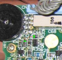
|
|
|
|
|