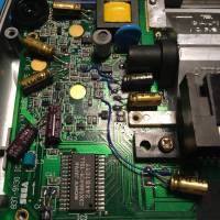
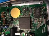
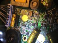
I recently bought a second-hand Game Gear that was listed as untested, so that I could try to recap/repair (as a hobby). Unfortunately, although the GG looked quite good, the capacitors had leaked all over the part of the board that handles, among other things, the display contrast.
I immediately removed the caps and cleaned thoroughly with IPA, and then proceeded to recap. I used high quality caps (nichicon) with the same capacitance and higher voltage rating, and I've used them before so I know they are good. The screen was showing some weird issues like you see in the video below
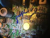
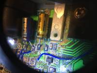
I then started fault finding using a reference GG with a multimeter in diode mode, and found a free pad and a corroded via, so I jump-wired the points that were not having continuity using 30 gauge wire.
Even after this, the screen had the same issue, although I'm not sure how this happened, at some point the screen worked properly, with the exception that when increasing the brightness beyond a certain threshold, there would be interference on the screen. It was then I decided to reflow everything to remove any corrosion and the screen went back to what you see in the video.
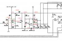
As far as I can tell, if I make voltage measurements, everything seems fine, but when I used diode mode with the black end on ground, I still find discrepancies as you can see in the linked schematic. When two values are present, the left one is from the reference GG.
I'm running out of ideas. It feels like the problem might be some problematic diode, or transistor, but when checking these, in circuit, using diode mode, they seems fine, unless the issues show up with higher voltages.
EDIT: Things I've tried:
Continuity between several points, as well as front and back via continuity.
Pushed on different components, including fiddling with the ribbon cable, but no effect.
Wow, after spending many hours trying to find the issue and nearly losing hope, I went through the whole left side of the board and noted down the diode mode readings on both GGs. I was mostly focusing on the difference in the reading of 0.86/0.66, but in the end, the OL you see on the left should have caught my attention earlier. There was another corroded via which was breaking continuity between Q8 and C51/R36. After I jump-wired the connection, to my amazement, the GG worked completely fine!
I hope the diagram with readings can come in handy for other people too.
Amazing, congratulation! A great project with a happy end. I remember how it felt when I first recapped my GG and saw that it worked what I did. When I was a kid I would have never imagined I would be able to do something like this. So I understand your success.
If you have time, I wonder if you could make a youtube or picture tutorial explaining your procedure. Your skills in this are beyond my and I understand half of what you explained. So here is an example what would be interesting for someone like me
- I know how to measure voltage/ampere with a multimeter, but dont know what diode mode is and how to use it. What does OL mean and how do you know if voltages are similar enough?
- How do you find the correspondence between the schematic images and the actual pins in the hardware. How to read it. Which things you measure, in which order, and why. Where to find the schematic images.
- It would be good to see the whole procedure and how to do it systematically with the two devices in practice on a GG.
Just a suggestion, only if you want and have time.