|
|
ForumsSega Master System / Mark III / Game GearSG-1000 / SC-3000 / SF-7000 / OMV |
Home - Forums - Games - Scans - Maps - Cheats - Credits Music - Videos - Development - Hacks - Translations - Homebrew |
View topic - Capture Game Gear GG-MAIN 837-7398-03 bar on screen.
 |
| Author | Message |
|---|---|
|
Capture Game Gear GG-MAIN 837-7398-03 bar on screen.
Last edited by Voodooween on Fri Apr 19, 2024 5:07 pm; edited 4 times in total |
|
Hello,
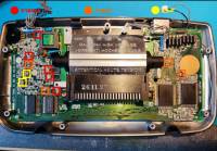
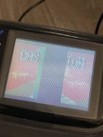
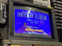
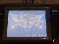
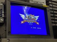
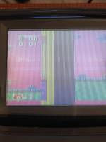
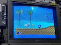
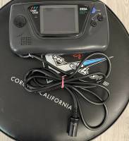
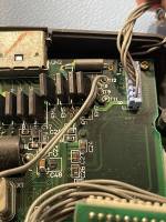
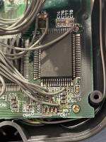
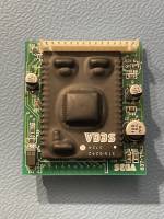
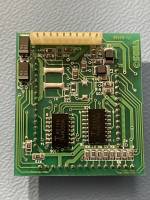
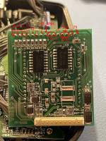
I recently acquired a Sega Game Gear Capture kit from a British developer, so obviously I had to recap the console. I did the ceramic method to recap that VA0 board (I included a picture of the guide I followed) the 1st picture is what happens when I power up the console with no cartridge at all. The 2nd one is the guide I followed for the ceramic recap. 3rd and 4th are with Castle of Illusion on the Game Gear and the TV. You can see the bar on the middle of the Game Gear screen. 5th and 6th with Game Gear Sonic 2 on the Game Gear and the TV. You can see there is no bar with that game. I tried Game Gear Shinobi, Sonic Chaos and Sonic Triple Trouble as well and all of these 3 games are working flawlessly on the Game Gear Screen. 7th and 8th is Sonic 1 with the Master Gear converter, you can see the colour are wrong on the Game Gear and I have the bar on the middle of the Game Gear screen as well. Could it be a failing screen or something else? Because I find that a little bit weird that some game are working fine when some aren't. I am using a "Sega 1602-18" European (French) PSU. Edit : I just learned that Castle of Illusion on Game Gear is actually just a Master System game. Could it be a problem about the SMS on the game gear itself? But then I don't understand why it would work perfectly on the TV. 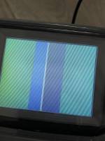
|
|
|
|
|
|
|
| So what you are seeing is that it works fine for GG mode games, but SMS mode games show a screen with bars in the middle, the left and right edges of the SMS mode screen, and the wrong palette. I guess owners of similar devices can comment on what they see in this scenario, but I suspect it is working as intended. | |
|
|
|
|
|
| An unrelated observation: the chip is marked 315-5242 which matches the number of a chip used in Sega arcade games as a video DAC. Modern recreations have been made to replace failed chips: https://caiusarcade.blogspot.com/2020/07/sega-315-5242-reproduction.html | |
|
|
|
|
|
|
The LCD is divided into three different columns, each driven by a separate chip on glass:
https://www.smspower.org/forums/files/lcd_layout_186.jpg It appears in SMS mode that the clock driving the middle chip might be messed up. It would help to see a picture of how the video board is wired into the main board and which contact points the wires go. There is a pin on the ASIC that puts the GG into TV Out mode, this is used by LCD mods to get fullscreen SMS output but it changes the clock in a way that is incompatible with the LCD, I wonder if it is enabling this pin. |
|
|
|
|
|
|
| It seems to be driving the two sides with unscaled pixels from the SMS tilemap, so even if the middle was driven, large chunks of the picture would be missing. | |
|
|
|
|
|
|
I actually found the problem and as Maxim said it is actually working as intended.
There is a jumper wire from T10 to T11 that is not present on a non modified board and when removing that wire the SMS system works perfectly, but the capture board is not power on anymore. I also included multiple pictures of the wiring on the pcb. Do you think it would be possible to find an alternative and have the SMS working while having the capture board power on? 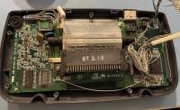
|
|
|
|
|
|
|
|
T10 is wired to the TV out enable pin on the ASIC, so basically it's working exactly like every other TV out mod.
There's no way to make that work with an original LCD as it changes the pixel clock in a way that is not compatible. It may work with a newer LCD mod as they enable the same pin. (though given some have HDMI out support that may be redundant) |
|
|
|
|
|
|
Oh okay. I'll leave it as is honestly, I am not really interested about modding a development kit when it is possible to add modern VGA/HDMI capture mod on any gamegear anyway. So I guess later capture kit (B4U serial, VA1 board) would also have that problem? |
|
|
|
|