|
|
ForumsSega Master System / Mark III / Game GearSG-1000 / SC-3000 / SF-7000 / OMV |
Home - Forums - Games - Scans - Maps - Cheats - Credits Music - Videos - Development - Hacks - Translations - Homebrew |
View topic - gamegear still have problems after cap replacement...
 |
| Author | Message |
|---|---|
|
gamegear still have problems after cap replacement...
|
|
long story short:
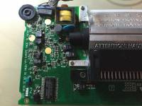
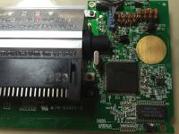
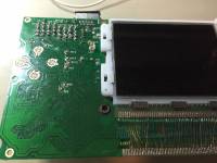
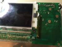
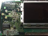
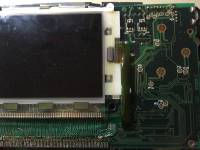
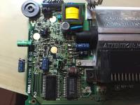
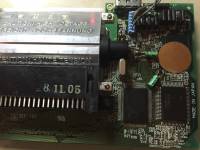
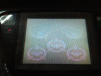
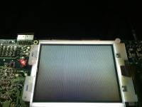
i have a game gear since i was 15, played with it a lot. few years ago i did the capacitor replacement, with great improvements on video/audio. out of the blu few months ago i get no images on the lcd, but the game works with audio, and i can play it, of course without image ;D than i've bought 2 spare gg for few euros,hoping i could using them to fix the issue. one was working but had lot of dead pixels on screen and classic lcd problems, but same motherboard as mine the other one has different motherboard with 2 chip, and no sign of life ;) what i did to try to fix mine with no success with flux and new solder paste i re-soldered every component on the mobo (sega chip included, and checked it with a microscope if it was some short on micro pins), but still no image. i've got a second set of capacitors, but the result is the same: no image i've checked lot of traces sarting from the replaced cap if there was a broken one, but i didn't find any. i also compared (the working "twin" spare and mine, both powered off) every resistor and capacitor reads with the multimeter in ohm mode and diode mode. almost same values on both motherboards. swapped all 3 lcd to check if my lcd was faulty, first simlpy desoldering the flat cable and swapping the lcd,than also resoldering with 01mm copper enamelled wire directly to the pinout on lcd: all the lcds are fine and 100% working (of course one has lot of dead pixels but is working), so it was no lcd problem. i (temporarily) gave up with my mobo and simply recapped the spare motherboard and re-soldered my lcd on it, so at least i have a working gg, but i would try to understand if i can fix at least another one. the current situation is: my original mobo, working audio (with the dead pixels lcd on it)but still no image (i've attached the pic mine1-4). i noticed the brightness potentiometer doesn't work anymore,no brightness change if i rotate it, but i don't think is faulty because also shorting pin 2-3 (it sould fix brigthness at 75%) doesn't make any difference the second spare (the one that was dead) resoldered and recapped, apparently is working better than mine because i can see a really fainted image on it, with no color (spare1-4). i also attached a screen compare between the working gear, and the defective image i get on the spare. any help on both? what i could check to fix at least one of them? what else could i try? p.s. i'm using original sony psu, and screen connector wires are ok and no sign of short,same for the replaced cap. my motherboard now has original cap, but same issues happens with new ones. |
|
|
|
|
|
|
| It looks like the board is covered in the leaked junk on the 1/2/Start side, you'll want to wash the board in that area. Toothbrush will work pretty good in getting stuff off the board. | |
|
|
|
|
|
if you mean the pic mine-1.JPG there is a solder residue on the big pin on the left, that doesn't give any working problem (is there since the first recap i did years ago), if you mean other "junk" i guess it was just flex residue after the re-soldering. cleaning the board(s) with toothbrush and alchool doesn't gave any improvements, still same issues. any other clues? |
|
|
|
|
|
|
| Both 1 and 3. If cleaning doesn't help then most probably some via has corroded through or one of the SMD resistor or capacitors has got damaged. These resistors are very fragile at their edges. | |
|
|
|
|
|
|
problem is: which one is damaged?
i've tested almost any resistor/cap comparing the readings and the values are almost the same, so i'm clueless... |
|
|
|
|
|
|
|
Ne1 can help me out?
Any advice? Thx |
|
|
|
|
|
|
|
If you've tested your caps and resistors like you said and they're ok, then it might be a faulty transistor.
I've been going through my old game gears lately and fixing them up. I have 3/4 more or less fully functional, but the last one I'm working on has an issue similar to your spare, a really dim screen and isn't playable because of it. I'm not an electrician, but looking through a schematic I found and testing voltage readings between my bad game gear and another of the same model that works, I noticed that the Q6 transistor gives me different voltage readings across the game gears (about a 15% difference), which leads to later components doing the same. This is my best guess as to what the problem is with my game gear, a faulty transistor. Fixing my unit isn't very high on my to-do list since I have 3 more that work fine, but if you haven't fixed either of your gears when I get around to replacing this part, then I'll let you know how it goes. |
|
|
|
|
|
|
|
thnx for reply, i'll have a try testing the transistors to check if the readings are ok.
can you help me out on readings? i suppose i have to test it with powered on unit... which pin i have to check? i'm not an expert electrician so a good tip is welcome ;) |
|
|
|
|
|
|
|
I'm by no means an electrician myself. If you can desolder the transistors then you should look up some tutorials on how to check them on youtube using a multimeter. Based on the part number in the schematic the Q6 transistor should be of the NPN variety as far as I can tell. I think you should start by checking that transistor since your circuit board looks very similar to mine in your spare.
If you want to try something similar to what I did to test things then I can tell you that out of my working game gear I was getting 20.5 and 21.1 volts DC output when I checked the transistor legs (positive lead on the middle leg, negative lead on the outer legs, one at a time, game gear powered on). My bad game gear gave me readings of 19.1 and 19.7 volts. If you do try this I recommend putting electrical tape over your leads so just the very tip is exposed to help prevent any short circuiting. Also, keep in mind that my game gear models are US, so I don't know how reliable of a measure comparing voltages with me will be if you take that route. I've attached a pic of the relevant part of my mobo for you to compare if you want. |
|
|
|
|
|
|
|
i did some readings on the transistors and the diodes
the voltage readings i get from both "legs" on the non working one, and the working one (same power board, same game on both) q6 15,27 16,14 15.5 16,5 q5 5,8 17,20 5,92 17 q8 -9,09 -7,96 -9,93 -8,9 q9 7,9 9,16 8,93 10 q10 -2,70 -6,90 -12,45 -10,18 q11 1,35 1,53 10,36 12 q7 4,34 4,46 0,47 0,1 d4 0,47 7,24 0,21 7,37 d2 0,76 1,50 2,27 8,37 d1 -0,02 -0,23 -0 -0,50 d3 0,45 2,70 1,25 8,36 from the readings i can see the q10, q11 and q7 gives the most different values, but replacing them does't change the values. i dunno if is a single faulty component or more than one. any clues? thnx |
|
|
|
|
|
|
| Just a heads up, I realized most of the transistors caps and resistors I was looking at are linked to the brightness knob, i.e., these components will output more voltage when the screen is brighter. I'll need to do some more comparisons later with both of the knobs turned up all the way. | |
|
|
|
|
|
| After going through voltage readings again, I noticed that on the C54 capacitor (corresponds to the 0.47 uf cap that is hanging off the board on your spare) I was getting 3.8V DC on my working one, and 2.0V DC on my bad one. I changed the cap out to make sure that wasn't the problem (it wasn't), so my guess right now is that a nearby transistor is causing the problem. I have some better tools on the way here, so I'll do some more testing when they arrive. | |
|
|
|
|
|
|
i've noticed too the brightness knob affects the readings of all the transistors.
keep me posted with your readings/result, so maybe it can help me fix mine. btw which tools did you buy? |
|
|
|
|
|
|
| Just some better tweezers so I can pull out some of these tiny components when I desolder them. | |
|
|
|
|
|
|
Got my tweezers in and measured some parts.
Q8, Q9, Q10, Q11 - looked up the part info for the two types of transistors (2SA812 and 2SC1623) to see which pins were the emitter, collector, and base. Used the diode test on the multimeter; they all appear to be in working order. Broke two of the legs on Q10 so I'll need to get a replacement if I plan on getting the GG working again. R45 - tested at 1 Mohm (good) R47 - tested at 22 kohm (good) C57 - my multimeter isn't sensitive enough to get a reliable measurement, but I was getting readings around 60 pF, which is in the ballpark (probably good) I'll test out some more components tomorrow. |
|
|
|
|
|
|
|
R46 - 21.8 kohm (good)
C56 - ~60 pF (same issue as C57) (probably good) D2 - good (lifted a pad, but it's not connected to a trace. Looks like Sega used the same type of diode throughout the board to save on cost even though 3 legs were not always needed) D3 - good That's the part of the board where I was most expecting to find a bad component, and I found none. I'll check a few more, but if I don't find any bad ones I'm going to chalk this up to a faulty LCD or a problem that I'm incapable of fixing right now. |
|
|
|
|
|
|
|
My C17 SMD capacitor was measuring at 600 pF instead of 1200, so I ordered a replacement.
It doesn't look like my troubleshooting is going to help fix either of your GGs, so I'll refrain from posting anything else unless I think it could be helpful to you. |
|
|
|
|
|
|
|
ok, thanx a lot for the help!
keep me posted |
|
|
|
|
|
|
| I got McWill's kit to upgrade my screen, so I tried my problem Game Gear first. The new screen works great (and looks amazing), so it turns out the old screen was just fried. | |
|
|
|
|
|
| i'm happy for you, but unfortunaltey for me the problem is probably somewhere else. because swapping the lcd on the working board,works fine | |
|
|
|
|
|
| Hi...i am a new user here. In my case i found and testing voltage readings between my bad game gear and another of the same model that works, I noticed that the Q6 transistor gives me different voltage readings across the game gears, which leads to later components doing the same. | |
|
|
|
|
|
I believe the Q6 transistor is linked to the brightness knob, which will lead to different values across components if the brightness levels are not set identically on both Game Gears. Either way, this shouldn't affect the screen from working. |
|
|
|
|
|
Update
|
|
If anyone runs into this issue in the future, i.e., screen not working after a recap but the game is running, then I recommend checking out the LCD Circuit section of the RetroSix Wiki for Game Gears: https://www.retrosix.wiki/lcd-circuit-game-gear
I was working on a Game Gear with these symptoms today. The wiki mentioned that there should be continuity between C37 and C52 for a two ASIC model. There was no continuity between these points, and I was quickly able to pinpoint the break to a corroded via. The screen came back online once I restored the connection. Probably saved me quite a bit of time tracking down the problem. |
|
|
|
 |

![20170303_134641[1].jpg](files/thumbs/t_20170303_1346411_213.jpg)