|
|
ForumsSega Master System / Mark III / Game GearSG-1000 / SC-3000 / SF-7000 / OMV |
Home - Forums - Games - Scans - Maps - Cheats - Credits Music - Videos - Development - Hacks - Translations - Homebrew |
View topic - SG 1000 II, SEGA MARK III and JAP SMS - Schematic
 |
| Author | Message |
|---|---|
|
SG 1000 II, SEGA MARK III and JAP SMS - Schematic
Last edited by Esrael on Sat Dec 31, 2016 2:52 pm; edited 5 times in total |
|
Recently I bought a SEGA Mark III and didn't find any schematic for it.
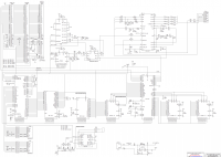
I have opened my console and did a schematic from it. The names for signals is based in the schematic of Tec Toy Power Base. Notice: The schematic can not be 100% accuracy, since this was done following board traces. Edit: 19/01/2016: NMI signal from VDP IC is only used for Pause Switch. Removed trace which goes to bus. Edit: 04/03/2016: Added Japanese SMS Schematic, another schematic done following board traces. Missing some pin names on SEGA I/O 315-5297. Edit: 04/12/2016: Added SEGA MARK II / SG 1000 II Schematic, another schematic done following board traces. Missing some pin names on SEGA 315-5066. 
![esquema_sega_mark_ii[1].png](files/thumbs/t_esquema_sega_mark_ii1_159.png)
|
|
|
|
|
|
|
| This is great ! | |
|
|
|
|
|
| very nice, thanks for sharing :) | |
|
|
|
|
JAP SMS - Schematic
|
|
Japanese SMS Schematic, added to main post.
Done in the same way as Sega Mark III, following board traces. |
|
|
|
|
|
|
|
Why would Sega put !MREQ on B10 on one system, on B9 on the other? Are you sure that one got traced correctly?
Philipp |
|
|
|
|
|
|
I had noticed these differences too and rechecked traces and this is true. Card Slot has some differences too in pin out between Mark III and Jap SMS eg: Pin B2 in Cartridge Slot on Mark III is !CSCN4 and Jap SMS is assigned to VCC, Pin 13 on Card Slot in Mark III is assigned to !MREQ through a gate IC and assigned to !CE 2 like an export SMS. Edit: Searching I have found others docs which can confirm these differences: - SEGA MARK III -> http://cgfm2.emuviews.com/txt/m3tech.txt - Japanese SMS -> http://www.smspower.org/forums/15109-3155297AndMoreJapaneseMSStuffPinout |
|
|
|
|
|
|
|
Cartridge pin B20 seems to be missing in your SMS schematic.
Philipp P.S.: I used your schematics to make a cartridge pinout table at http://www.smspower.org/Development/JapaneseSMSCartridge |
|
|
|
|
|
|
Thanks. B20 has no connection. Updated schematic in Main Post. |
|
|
|
|
|
|
|
It's great work, I'm glad someone took the time to confirm (and even improve) the analysis I made using only board scans , pinout guessing game by following board traces is quite fun, right? ;-)
And yes,the reason of the differences between Mark III and MS cartridge connections is because MS has the ability to control the various chip selects from software while this is done by hardware on Mark III (but they should remain fully compatible from what I've looked in the other thread). |
|
|
|
|
|
|
Thanks. Yeah! that was fun. Some traces required a multimeter to arrive his destination, because goes under some ICs. I can't understand why I/O uses CSync Signal at pin 19 coming from VDP, I think this can be used for sync 3D, but external export / Mark III 3D adapter works without this signal. Other question your analysis say pin 62 (N.C.) from I/O is !CONT 2. Is possible which this pin can be used for software reset like !CONT does in export SMS? (Grounding this pin can confirm this but at risk of damaging I/O). |
|
|
|
|
|
|
| Csync is for autofire I think, I see no other clock pins. | |
|
|
|
|
|
|
So M1 really isn't available on a JP SMS cartridge connector?
Somehow I was sure was. Maybe I'm not remembering correctly. |
|
|
|
|
|
|
Retested again with a multimeter and !MI is only connected between Z80 pin 27 and Expansion connector pin 37. Rechecked B20 again and really no connection for this pin. |
|
|
|
|
|
Last edited by Charles MacDonald on Mon May 09, 2016 2:40 am; edited 3 times in total |
|
I did some tests and can confirm that pin 62 of the 315-5297 is mapped to bit 4 of I/O port $C1/$DD. When the pin is pulled low (I used a 1K ohm resistor) bit 4 goes low, otherwise when not connected or pulled high bit 4 remains high.
Bit 5 of port $DD is always 1 and seems to never change. I also checked port $F2. Bits 1,0 latch the last value written, bits 3,2 are always zero, and bits 7-5 are described below. Port $F2 isn't mirrored anywhere else. EDIT: Well this got interesting. Bits 7-5 of port $F2 return the high bits of a counter that is clocked by the C-Sync input into the 315-5297. The counter is 12 bits wide and counts up on each C-Sync pulse. The bits return are as follows: D7 : Counter bit 11 D6 : Counter bit 7 D5 : Counter bit 3 D4 : Always zero D3 : Always zero D2 : Always zero D1 : Mute control bit 1 D0 : Mute control bit 0 The mute settings are: 0,0 : PSG only (power-on default) 0,1 : FM only 1,0 : Both PSG and FM disabled 1,1 : Both PSG and FM enabled I'm not sure what the point of exposing the counter state like this is for, but it's there. As TmEE said the composite sync is used for the rapid fire feature and this counter is part of that. I also verified the rapid fire button does not function as an input that is mapped to port $DD, such that you can't read the state of the button when pressed. |
|
|
|
|
|
|
How the RAPID button works exactly? I've read that is possible to activate the function for a selected gamepad button, by "hold down the button then while it's held down press the rapid button". A figure of the JP SMS manual shows the Power LED blinking, but I couldn't get a good translation of the procedure. It blinks while the rapid fire function is active for a gamepad button? Or blinks only when the Rapid button is pressed?
Could be related with TH input? According to Enri's docs, bits 6 and 7 of I/O port $DD returns TH direction (input or output) of the controller ports on a JP SMS, instead the line state (low or high) like on a western SMS. A Light Phaser game could be released for JP SMS if it used bits 6/7 to detect that specific system and then use bits 4/5 (my hypothetical example) to read TH input. Also, Enri's docs don't mention mirrors of I/O ports $3E/$3F. Could you confirm if they don't exist on the JP SMS? -- Enik |
|
|
|
|
|
|
|
Did some more tests:
When rapid fire mode is enabled the LED is turned off for 2048 clock pulses and on for 2048 clock pulses. By clock pulse I mean C-Sync. The time that the LED is turned on or off is 131.461ms, and the total period is 262.924ms. The reason it isn't exactly 131.072ms or 262.144ms is due to the C-Sync signal having a period during the vertical sync pulse where there are no horizontal sync pulses. The rapid fire counter is only reset by the reset signal and is not synchronized to vertical sync or anything like that. Turning rapid fire on or off doesn't reset the counter, consider that it's free running all the time. How rapid fire mode works from a user perspective: Rapid fire mode is disabled when the reset signal is asserted (power-on). At this time the LED remains lit. To enable it, press and hold the Rapid fire button, and then press button 1 or 2. The LED will start blinking, and now you can let go of the rapid fire button. At any point later on you can press and hold the rapid fire button and then press button 1 or 2 to disable rapid fire mode. Rapid fire works for both buttons 1 and 2 but not any of the directions. The LED blinks as long as any controller's buttons have rapid fire applied. Here are some examples: Reset -> Hold Rapid, Press 1 (LED starts blinking) -> Release Rapid
(Now button 1 has rapid fire) Hold Rapid, Press 2 (LED continues to blink) -> Release Rapid (Now buttons 1 and 2 have rapid fire) Hold Rapid, Press button 1 then button 2 (LED stays lit) -> Release Rapid (Now rapid fire is disabled) All of this works for the 2nd controller port too, so at most you can toggle rapid fire on for all four buttons (1,2 on 1st port, 1,2 on 2nd port). EDIT: More tests When the TH pins are configured as inputs via port $3F, bits 7,6 of port $DD returns their corresponding pin state unmodified. There seem to be internal pull-up resistors so an unconnected pad reads as all inputs high. When the TH pins are configured as outputs via port $3F, bits 7,6 of port $DD are always zero regardless of the TH pins being pulled high or low. This seems to match what I saw in the Genesis, where if you select the JP region those bits are always zero no matter what. The I/O control register is only mapped to $3F and the memory control register is only mapped to $3E. Writing to any address within $00-$3D does nothing. I made a mistake earlier, pin 62 corresponds to bit 4 of port $DD, I said "bit 5" before. This input is not affected by any combination of the TH control bits in port $3F (direction or level). I corrected the earlier post. |
|
|
|
|
|
|
Bit 4 of port $DD on Export SMS is assigned to Soft Reset function. But I think SEGA leave this function unused since some Japanese games does not have a Software Reset routine or I am wrong? |
|
|
|
|
|
|
Thanks very much for your works, Charles and Esrael, very appreciated.
Forgive my ignorance on video signals, I'm trying to understand what clock drives the C-Sync signal. I've read that C-Sync is H-Sync ANDed with V-Sync. 2048 clock pulses divided by 131.072ms (the lesser time) gives me 15625Hz. NTSC horizontal frequency alone has a higher value (15734 kHz). What I'm missing? When a controller's button has rapid fire, may I assume it goes low/high at the same time the LED is turned on/off?
So, games can read TH input the standard way, but there are reports about Light Phaser not working on the SMSJ. The gun also needs to signal the VDP to latch the HCount value, but as seen on the schematic the !HL (or NHL) line connects the 315-5297 with the VDP. What else could prevent the Light Phaser from working on the SMSJ?
You also wrote:
But listed bits 7-5 as returning the counter bits. Shall I assume as 7-5? Is this 12-bit counter internal only or is readable in some way? I have another curiosity about the SMSJ: the embedded 3D adapter remains functional when a discrete 3D adapter is inserted into the card slot? |
|
|
|
|
|
|
It's a little hard to check this accurately since there's no pixel clock I can use and trying to probe the 10.583 MHz clock prevents it from oscillating. If I use the Z80 3.58 MHz clock as a reference, the period for the LED to flash is 941,184 cycles. At 280ns per Z80 clock, that's 262.933ms. The frame rate is 5.36 MHz / 262 lines per frame / 342 pixels per line for 59.92 Hz, or 16.688ms. The LED flash time (262.933ms) divided by the frame rate (16.688ms) is 15.755 frames. 4096 counts divided by 15.755 frames is 260 counts per frame. Now the C-Sync signal is pulsed 258 times per 262-line frame, which is sort of close to 260, so I think they roughly agree. What do you think? About testing the counter, I had disconnected the C-Sync input to the custom chip and instead connected the port $F2 bit 0 output to it, such that I could toggle that bit and manually clock the counter. That's how I determined it took 4096 pulses before the sequence repeated.
I haven't checked yet, though I suspect this will be easy to tell by comparing the rate at which TL/TR toggle relative to the accessible counter bits in port $F2.
Does that mean no light phaser games work on the SMSJ at all? Or just some don't? I hadn't heard about incompatibility issues before.
Thanks for noticing that, it was a typo. I've edited the previous post to correct it. The counter is internal and some of the outputs go to port $F2, but not all of them.
Hmm, that's a good question. I'd imagine both would work in parallel? But some testing is needed to be sure. |
|
|
|
|
|
|
Yes, they roughly agree.
Some users stated it doesn't work in general. I did a quick search and found Missile Defense 3-D and Rescue Mission as examples. I also found a report of the problem on the Japanese Mega Drive as well. There are some mentions about TH signal being inverted on the JP systems, what was always seemed like a mistake to me.
I've read that it would be a way for 2 persons watch a 3D game at same time, but I didn't found information about any test performed. |
|
|
|
|
|
Last edited by Esrael on Tue May 10, 2016 3:37 pm; edited 2 times in total |
I have a Tec Toy Mega Drive with Region Switch and My Light Phaser worked when running in Jap Mode with Hang On/Safari Hunt and Gangster Town. To confirm which my Mega Drive are running in Jap Mode I have used "Mônica na Terra dos Monstros" which show Sega Mark III Logo. I don't have an adapter to test Light Phaser Games on my Japanese SMS, but based on my tests when trying to add Light Phaser (with success) support for Game Gear in both Ports A and B, using a Scope and pointing Light Phaser to TV screen I can see !HL / NHL pulse going to VDP without this pulse Light Phaser only Hit screen at fixed X Pos. The idea is using a Light Phaser Game on JAP SMS and test if !HL signal is send to VDP. Edit: The Game tested on Mega Drive was Safari Hunt from Hang-On/Safari Hunt cartridge not Hang-On. |
|
|
|
|
|
|
|
OK, I'll definitely test if the I/O chip is asserting !HL in response to TH from the light gun. And I'll verify if the outputs are inverted or not too
It's pretty interesting that there would be this difference between the two systems. I wonder what's going on. |
|
|
|
|
|
|
Could you also measure the TL/TR toggle rate of the rapid function and run Flubba's SMS VDP tests on the SMSJ? There's a test about "HC change on TH 0->1" that latches the counter via software, but I'm interested to known about any test that fail on the console. |
|
|
|
|
|
|
|
Got my 3D glasses + adapter today:
SMSJ built-in port: Bit 0 of $FFFB only controls the glasses. Other locations do not affect it. SMS adapter port: Bit 0 of $FFF8,9,A,B control the glasses. The adapter has a jumper with two positions "M4" and "M3". Default is "M4", which connects input C of the 74HC259 to card pin 3 (MREQ) which is appropriate for the US SMS and SMSJ. If you select "M3" then it is connected to the card pin 13 (MREQ 2) which is appropriate for the Mark III. SMSJ + adapter: It works the same as above, so the US adapter is 100% compatible with the SMSJ and does not interfere with the built-in glasses. In this case writing to $FFFB affects both pairs of glasses simultaneously, and $FFF8,9,A affect only the glasses plugged into the 3D adapter. When the reset signal is asserted both shutters are off (transparent). Afterward if you don't write to $FFFB to initialize anything the default state has the left shutter on and the right shutter off. I did some experiments changing the shutter state on line $40 and back on line $80. As expected this makes one eye only see those lines and the rest of the screen is black, and the other eye can only see lines $00-$3F/$80-$BF and lines $40-$7F are blank. The exact border where the glasses turn on and off is poorly defined so don't get sharp transitions. It takes around 10 scanlines for the display to transition from fully visible to fully obscured by the shutter. So you can't make changes to the 3D effect within a frame. Likewise pulsing the shutter state for an interval less than a few scanlines shows that the shutter fills in from the interior towards the exterior in rather unusual blobby shapes. So it's not instantaneous, nor does it fill in cleanly from top to bottom or left to right. Enik: Flubba's test works, all cases are OK including the TH test you mentioned. To make his ROM work on a SMSJ I just had to remove the lines relating to port $3E. I wrote a test program which set the TH pins to inputs, polled the TH bit to check for the lightgun beam detection, and wrote the H counter to the display as well as making a sprite track the X position. It works just fine on a US SMS and the SMSJ. So if there's some kind of incompatibility I'm not sure what it is yet. |
|
|
|
|
|
|
I'm impressed with your experiments, wasn't expecting full analysis of the 3d glasses + adapter.
Both shutters are off on reset, despite being set as left=on/right=off by default (set to 0 according to SMS Power Wiki), so the first effective change occurs when the state is changed to 1 (left=off/right=on)?
Most of the times games change the shutter state after VINT occurs, at end of the frame. However, as I commented in MAME sources, "there are occurrences when Sega Scope's state changes after VBLANK, or at active screen. Most cases are solid-color frames of scene transitions, but one exception is the first frame of Zaxxon 3-D's title screen".
Thanks! I guess you are using the expansion slot, that is disabled by those lines.
Well, I think your tests covered the required functionality. Any SMSJ / MDJ user here to confirm the reported Light Phaser compatibility problems? |
|
|
|
|
|
|
I never got the Light Phaser to work on my Japanese SMS. Haven't tried on my Japanese Mega Drive and unfortunately I don't have a Light Phaser any more so I can't test that. |
|
|
|
|
|
|
| My main SMS is a Japanese MK-2000 and all the light gun games I've tried work perfect. I was used an Everdrive though...I don't have any original light gun MKIII games. Was there a specific problem people were having? | |
|
|
|
|
|
That's because they don't exist. |
|
|
|
|
|
Last edited by enik on Sun May 22, 2016 11:47 pm; edited 1 time in total |
Did you test that Light Phaser with other SMS/MD version to confirm it was working? |
|
|
|
|
|
|
Okay...but what about your light gun issue? |
|
|
|
|
|
|
It didn't work period, at least from what I remember. This was with both real SMS carts and the Everdrive. |
|
|
|
|
|
|
|
I had issues with certain roms, but for the most part, both my SMS light guns always worked with my MK-2000 (as well as all my US consoles).
The game (rom) that's given me the most trouble was Assault City. The original cart always worked perfect, but some roms wouldn't register hits on the screen at all. There's actually two versions of that game, but it's VERY obvious to tell which supported the light gun, so I wasn't just using the wrong version. I eventually found a working rom though, in SmokeMonster's romset. It sounds like you probably just had a bad gun. It happens. |
|
|
|
|
|
|
| Maybe you two were using different SMS->MKIII adapters that route some signals differently? | |
|
|
|
|
|
Thanks for doing all these tests, this is quite interesting. For completeness, did you verify if ports $DC/$DD are mirrored elsewhere and if port $3E can disable those ports like on export Master System model? |
|
|
|
|
|
Last edited by Charles MacDonald on Sun Jun 12, 2016 7:13 am; edited 2 times in total |
Checked again, the only mirrors for the joypad ports are $C0/$C1 and $DC/DD. You can also disable those ports by clearing bit 2 of port $3E. This does not affect port $F2 so you can still read the FM status and the rapid fire counter. Ports $3E and $3F don't seem to be mirrored anywhere else as far as I can tell. For the rapid fire I saved the button state once per frame in a list, and printed the list to the screen after 256 consecutive frames. In general this showed that the button state toggled every frame (30 Hz). I also kept a count of how many frames the button was low for and how many it was high for, and got 128 low and 128 high after 256 frames. Now sometimes the button state was low or twice for two consecutive frames. However within 256 frames it would always happen enough times to even the result out, so if you got a button state of 1,1 somewhere, you'd get 0,0 later. I think this is due to the slightly irregular timing of composite sync clocking the rapid fire counter. Looking at the data printed this happens every 64 frames, I'm not sure if we really need this kind of detail however. :D |
|
|
|
|
|
|
Good question, I tested it again and can confirm: After reset : Left shutter opaque, right shutter transparent (same as $FFFB=0) Write $FFFB=0 : Left shutter opaque, right shutter transparent. Write $FFFB=1 Left shutter transparent, right shutter opaque. So the first effective change is when you write $FFFB=1 as you said. I realized I could disconnect the !HL input on the VDP and use it to probe other signals to determine the H counter value when they are active. I used an inverter to capture the timing for the opposite edge too. Reading port $7F: !CBT - Goes low at $F7, high at $FE (7 counts, 14 pixels, 28 cycles of the 10.7368 MHz clock) !PCP - Goes low at $F9, high at $00 (7 counts, 14 pixels, 28 cycles) !CSYNC - Goes low at $E9, high at $F6 (14 counts, 28 pixels, 56 cycles (horizontal sync pulse only)) !NMI - Goes low at $F6 at one frame, and high at $F6 of the next The pulse widths match my earlier results (in m3tech.txt) and disagree with my much older H counter tests (in msvdp.txt), so likely the old ones were a misinterpretation of the test results at the time. I'll look into it further. Also it seems the !HL input latches the H counter at the negative edge, so it functions as a negative-edge triggered register and not a transparent latch like I had thought in my Mark III tests. I'll check again but as the VDP is the same between them I think this description is accurate. |
|
|
|
|
|
|
The button state probably changes each 256 pulses. Considering 260 pulses per frame, there's a difference of 4 pulses. After each 64 frames, the accumulated difference will cause two state changes in a same frame, seems to be the duplicated values got on your tests.
Considering 258 pulses per frame, the repetitive values would occur each 128 frames. Is there a chance for the count be in fact 260 instead 258? |
|
|
|
|
|
GND case?
|
|
What's inside the GND case near the SCART output?
Philipp |
|
|
|
|
|
|
|
SEGA Mark II / SG 1000 II Schematic, added to main post.
Done in the same way as Sega Mark III, following board traces. Revised schematics -> http://esraelneto.com.br/esquemas.php |
|
|
|
|
|
|
I'm gonna have to eat crow now, because I got a Light Phaser again today and sure enough, it works just fine with my Japanese SMS. |
|
|
|
|
|
|
| Those light guns are really temperamental. I think to get consistent performance, we probably need to "refurbish" ours; Clean the sensor, check all solder connections, etc. I still have the one that sometimes works perfectly and other times barely works at all (on the same monitor, etc). | |
|
|
|
|
|
| It might be the photodiode, I've done everything from cleaning it to replacing the two capacitors inside and nothing seems to help adjust the sensitivity. I really have to crank up the contrast on my monitor just to even get it to register shots, and even then it doesn't work well. | |
|
|
|
|
|
|
Hello! i'm stuck with this console (but maybe this post is too old)
on internet there is NO WAY to find any service manual for the Mark III (japan) i've VCC with 4.8 Volt VCC Digital with 4 Volt (is correct?) i've already check that all the IC receive voltage (4.8 and 4 on digital) Black picture on the screen, no sign of life... any clue? hope someone can help! thanks Riccardo |
|
|
|
|
|
SG 1000 II, SEGA MARK III and JAP SMS - Schematic
|
|
I don't understand if you're saying that you are measuring 4V DC or 4.8V DC on the power rail but both are a bit low. The output from the 7805 voltage regulator should be 5.0V DC or very close to it e.g. 4.95V DC.
Also, do you have a game cartridge inserted? |
|
|
|
|
|
|
I’ve 4.8 V DC on the VCC line And 4V DC on the VCC DIGITAL line So it’s really low… probably some fault… I’ll check today all the IC and keep you informed :) |
|
|
|
|