|
|
ForumsSega Master System / Mark III / Game GearSG-1000 / SC-3000 / SF-7000 / OMV |
Home - Forums - Games - Scans - Maps - Cheats - Credits Music - Videos - Development - Hacks - Translations - Homebrew |
View topic - What do R47uf 50v caps do?
 |
| Author | Message |
|---|---|
|
What do R47uf 50v caps do?
Last edited by Capt. 2110 on Sun Aug 17, 2014 4:20 pm; edited 1 time in total |
| I found a 1994 Game Gear with the following games: Taz-Mania, Dracula, and Ecco. The GG needs new caps and is kinda dinged up and Ecco is failing, but the seller wants me to make an offer. I'm thinking $10. How much is it worth? | |
|
|
|
|
|
| I also have to buy it today. I think the Ecco cart had dirty pins, because now it works fine. | |
|
|
|
|
|
| I bought it, I replaced all the caps, except the R47s. It still won't power on. What do the R47s do? | |
|
|
|
|
|
|
The 0.47uF 50 Volt capacitors are the main LCD layer control. They let more light through the layer from the tube back light.
Make sure you have got the right type it's 0.47uF. This the main problem capacitor set in the Game Gear change these first. |
|
|
|
|
|
|
|
I replaced them, but it still wont power on properly, what should I do now?
Pictures: I know the solder joints stink, I plan on fixing them later. What is the damaged resistor? 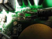
|
|
|
|
|
|
|
|
How certain are you that EVERY new cap is pointed the correct way? They are polarized.
Is the "damaged resistor" In the first picture? Check it with a multimeter to be certain, but it may still function. |
|
|
|
|
|
|
|
Yes, I checked twice on all of them. I'll check the resistor in a hour or two and report if it works or not..
Edit: The resistor is good, but I don't know the original rating, so it may still be bad. |
|
|
|
|
|
|
| The resistor is good. I confirmed it. | |
|
|
|
|
|
| Take your multimeter back out and switch to the diode tester. It may look like a diode or a sound wave or both. if you touch the probes together does it beep? If yes connect one probe to ground and one to vcc somewhere on the board where you know the names of the pins. If it beeps, you have a short somewhere and that will prohibit the console from booting. | |
|
|
|
|
|
| Where are the VCCs and grounds? | |
|
|
|
|
|
|
If you are getting auto turn off, less than a second, then it's the power board at fault.
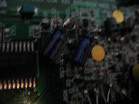
Caps look ok in the picture. one resistor would not stop it powering on. You can nearly remove every capacitor and it will still power on. So it's not a single component. |
|
|
|
|
|
|
| I have replaced the power board caps, what else could be dead? | |
|
|
|
|
|
They should be easy to find. For example: http://etim.net.au/ggtv/GGTV2-2ASIC.png |
|
|
|
|
|
|
| It didn't beep. | |
|
|
|
|
|
I see. We can at least cross of short from the list. Tell us again what exactly happens? battery power? External power? Lights, sounds? Also, use your continuity tester on the power switch to see if it connects correctly. |
|
|
|
|
|
|
| I plug the system in(or put in batteries, it doesn't matter), I insert a cartridge(or leave it out). I power it on, and the LED doesn't turn on, the LCD doesn't turn on, but the backlight does. And then it turns off after one second. | |
|
|
|
|
|
| I further tested the caps, but I don't get a reading on my oscilloscope. Am I doing it wrong? | |
|
|
|
|
|
You're not supposed to use an oscilloscope for testing caps, the tool you need is an ESR meter. |
|
|
|
|
|
|
|
I feel like you don't have a bad cap since they were all replaced. Look for shorts everywhere. Be patient and take special note of the places you added solder and to the power board.
In my experience, quick on/off power problems like you mention sounds like a short from positive and negative power. Do you get a pop sound on the speaker? Could be reverse current. |
|
|
|
|
|
|
| To my surprise, no pop! And I learned about the O-Scope later, I don't have an ESR meter. | |
|
|
|
|
|
|
If it was me I would find another power board, that you know is working and test the console this way. Caps on the power board really don't need to be changed as they are a different type to the main board.
If you're not getting any power on, then you can't test the caps if you have a meter or not. Yes you can test for a short, but I don't think this is the problem. one way to test is keep the 100uf top near the transformer connected and the 2 main 50 volt in place and remove the other caps one by one. The 10uf are for button control. The 33uf is for loading a game. If there is no problem, it will still power on even with all these removed. That way you will know exactly which is the problem area. Also check the speaker has not fallen out of it's mount and pressing on the main board. Happens a lot. The best way is to work on the main board out of the case. |
|
|
|
|
|
|
| Ok. I don't have another Power Board I can get to right now(My other GG has screw damage), but the speaker is not dislocated(I've pressed down on it, nothing happened and it looks normal). I'll do the caps later. | |
|
|
|
|
|
| I tried another power board and it didn't work. Would leaked electrolyte short something out on the board? | |
|
|
|
|
|
|
I cleaned the electrolyte and tested the caps for resistance on the 2K mode on my multimeter. These were the results.
Cleaning: GG powered on but lasted 3 seconds, started flashing the power light like the batteries were dead, and died. That's extra bad because I was using the AC adapter. Resistance check good GG: Both R47(.47uf) = Display doesn't change. 33uf = .305 10uf = .308 Another 10uf = Display doesn't change. Yet another 10uf = .305 No other caps were changed in the working unit. Resistance check dying GG: .47uf = No display change 33uf = .510 10uf = .510 Others were changed, I'm just too lazy to type them in. Which is the good one? |
|
|
|
|
|
|
|
Small Puny Update:
I'm buying new 0.47uf caps. Another update should be here around next Saturday. |
|
|
|
|
|
|
The caps came early and I replaced the .47uf caps. Again. And it still will not run... What else could bust up a Game Gear so badly?
|
|
|
|
|
|
What do all of the Game Gear caps do?
|
| Sorry if this has already been asked, but what do each of the Game Gear capacitors do? | |
|
|
|
|
|
|
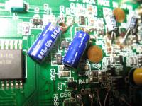
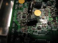
Looking at the picture the bottom capacitor looks bridged to the trace. You need to cut the cap legs shorter and solder them at the end, not half way up.
The caps. 100uf Power converter 22uf Brightness wheel 4.7uf Possibly secondary brightness stabiliser 0.47 The main LCD layer control 68uf Image 100uf Image 33uf Loading control 10uf Button control The Game Gear will not power up even if there is caustic acid on the board, there are allot of tiny hole through points and it can get to the other side of the board. Any short will make it not power on. |
|
|
|
|
|
|
| Ok, thanks! I re-soldered the caps shortly after I took the picture. How would I clean the acid on the board? | |
|
|
|
|
|
|
Neat or rubbing alcohol is the best way to disperse and clean the board.
You can get it in spray form isopropyl alcohol. Careful not to get any under the glass LCD are as it can be a pain to remove. I use a small brush usually supplied with the spay, and put some on the brush and work it around the parts. It will evaporate, so your left with a clean surface. |
|
|
|
|
|
Accidentally installed 4.7uf 35v backwards
|
|
Hi!
If I soldered the 4.7uf 35v cap backwards that is pos to neg and neg to pos and powered it on for the first time for a bit to test, would this damage my LCD? I recapped my GG Twin Asic 837-7938-01, and noticed I did C35 with 4.7uf 35v backwards, but after I fixed it there is blurry lines. I just want to determine if I was the one who damaged the LCD bc of the backward cap install at first or did I just have a bad LCD to begin with. What does C34 4.7uf 35v do? Prior to the recap the GG powers on a bit and then shuts off.I appreciate any opinion and advice. Thank you! 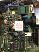
|
|
|
|
|
|
|
i'm sure glad you said that i almost install 47uf 50v caps!!! mine is working. ...well once i realized i was turning up the volume and NOT the contrast i could finally see. thank you. EDIT: not sure dude i've heard caps will sometimes explode if soldered in/installed backwards. |
|
|
|
|