|
|
ForumsSega Master System / Mark III / Game GearSG-1000 / SC-3000 / SF-7000 / OMV |
Home - Forums - Games - Scans - Maps - Cheats - Credits Music - Videos - Development - Hacks - Translations - Homebrew |
View topic - SMS FM Sound Expansion Boards (available now)
 |
Goto page Previous 1, 2, 3, 4, 5, 6 Next |
| Author | Message |
|---|---|
|
viletim!
|
|
I've been meaning to have a look at this. When I get time... |
|
|
|
| WB3 will only play FM on a Japanese system. | |
|
|
|
|
|
What about a PAL system thats in JAP mode?? |
|
|
|
|
|
|
| That should work. | |
|
|
|
|
|
| Yes, thats the problem im having, I switch my system to jap mode it shows the monster world 2 screen, but no FM sound :( | |
|
|
|
|
|
|
Viletim, i'll take one!
I've found a job! |
|
|
|
|
|
daco
|
adaptor
|
|
Will you make a Japanese cartridge adaptor and bios? I´m very intetested on them.
MANY THANKS. |
|
|
Re: adaptor
|
The following is speculation on the feasibility, not any kind of intention to actually do it: A cartridge adaptor would not be a huge amount of work design-wise or installation-wise, but almost no compatibility testing has been done in this area - the two connectors differ in many ways for certain purposes, eg. the SMS totally lacks the DRAM refresh pins to support BASIC cartridges. (It also lacks a keyboard so it's no great loss.) Getting a decent casing is very expensive, a small run of injection moulding does not come cheap. Retro-fitting to donor cart cases might be a possibility if the PCBs can be made accurately enough. I'm not sure how hard it is to make edge connectors, it's certainly an extra stage on top of a normal build. A BIOS mod would either involve bypassing it (almost certainly causing compatibility problems), or replacing it or piggybacking it (involving a lot of soldering and lifting at least one pin). It would be a lot harder than the plug-in FM board, but probably easier than the 20-wire version because the soldering would all be in one place. I'd guess there's probably as much demand for these sets as there is for the FM boards, but they won't be as academically interesting to build. |
|
|
|
|
|
|
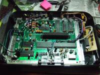
chucked mine in on the weekend. Very happy with it cheers. I still have the top and bottom shields on but they are getting, erm lighter lol.
|
|
|
|
|
|
|
Wow, your SMS pics and mods look sexy |
|
|
|
|
|
|
|
Thank you kind sir!
I am yet to re-do the S-video (amp), pause button mod and re-set button. I made some labels today on CAD for the switches. |
|
|
|
|
|
|
|
If you use Auto CAD can you send me the files, as my dad uses it for drawing up house plans and surveyors plots etc, I would like to make some labels for my switches too.
Also are you aussie omp? |
|
|
|
|
|
|
|
Hey Jacko yes I am from Australia. Brisbane. The CAD files are at work (I am an electrical drafter). They aren't anything exciting just 12mm (wide) x 20mm (high) with whatever text. I could even PDF it so you could open it in Adobe or whatever.
Heck I could just post it here as PDF so any ol' mate can grab it, doesn't worry me. |
|
|
|
|
|
|
You Little Ripper! |
|
|
|
|
|
|
|
Wow this is really awesome. I don't have much money at the moment but I'd be really interested in getting one of these down the track, if they're available still.
-MaRkiSH |
|
|
|
|
|
|
|
Here is a pic of what the labels look like.
Here is the file (zipped). 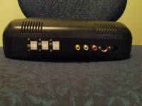
|
|
|
|
|
|
|
Ripper, gotta love the FM / AM some n00b would think its a futuristic radio now, hehe. |
|
|
|
|
|
|
|
Cool! Your SMS looks way better than mine modded one :-)...
FM/AM lol... hehe |
|
|
|
|
|
|
|
Just a quick check on how this works - will some games only produce FM sound when the console is running in Japanese mode via a language mod?
For example, will I only be able to get FM music on Wonderboy in Monster Land if I have Japanese text, too, or can I play with English text and FM music? |
|
|
|
|
|
|
The only game we cant get to work with the FM chip in jap mode is Wonderboy 3, eventhough when my system is in jap mode, the title screen has changed but no FM music.
No you can run it in english mode and still get FM sound... well at least I did anyway. |
|
|
|
|
|
FMtastic.
|
|
Thanks a lot viletim, I installed the FM board yesterday and it works great! I also installed a 50/60Hz switch. On top of that I'd planned to install a region/language switch but when I grounded pin 34 of the 315-5216 chip, nothing changed. Not sure what the deal was there. 2 out of 3 ain't bad though.
Now I just need an AV cable, or to install some AV ports in my SMS. -MaRkiSH |
|
|
|
|
|
|
| DAMN! I've been away from this stuff too long. Sold out I'm assuming? | |
|
|
|
|
zxfps
|
SMS FM Sound Expansion Boards
|
|
I have two questions about your FM board:
1. Where did you get the ym-2143's from. Do you get it from a seller or do you take apart Japanese SMS consoles? 2. As an alternative to soldering the inside of the SMS, can you solder the red output wire to an audio A/V cable (to plug into a TV) and have a stereo effect with PSG on one speaker and FM on the other? |
|
|
|
|
0. I'm not viletim
1. He bought them from a chip supplier. No, really. I think he mentioned somewhere that you can buy this stuff from Chinese suppliers now, whereas it was very hard to get 5 years ago. 2. No game uses the YM2413 and PSG at the same time. Only the Japanese BIOS does it. Thus, your stereo effect will be minimal. Some MSX people make use of the fact that the YM2413 outputs the tones and percussion on separate pins to make "stereo" versions, but I can't see much point to that either. |
|
|
|
|
|
|
Still available! Send me an email if you'd like to order one.
Yes, there are chinese B2B services for every type of product you can imagine. Though, I wouldn't go so far as to say that it was very hard to do 5 or even 10 years ago, you could simply ask a local parts importer to get some for you... The YM2413 been in production for over 20 years. There must be millions of them out there! The reason it's so hard to buy in single quantities is that few (none?) western products use it so it's not stocked as a spare part. I'm inclined to beleive that there would be a few spare parts suppliers in Japan who stock it. |
|
|
|
|
|
|
| Hey Maxim, not to be a jerk correcting you but doesn't Wonderboy III use both PSG and FM? I remember plugging it into my Japanese SMS years ago and it definitely sounded like a mix. | |
|
|
|
|
|
| Nope :) it just switches between 4-channel PSG and 4-channel FM. | |
|
|
|
|
|
B have you had issues trying to get FM to work with this game?? I cant get it to work either. |
|
|
|
|
|
viletim!
|
|
It doesn't work because, like Time Soldiers, it doesn't set bit 2 of $3E (I/O chip disable) before attempting to detect the FM hardware. Maybe the japanese SMS has better address decoding... |
|
|
|
|
I haven't had any problems with Wonder Boy III because I use a Japanese SMS with an adapter, not the new expansion board (yet :D).
In my case, Time Soldiers (US) still does not work, neither does Lord of the Sword or Out Run (US), but that is all due to the games not booting at all. Also, one weird issue is that with Rescue Mission, the Phaser doesn't register on screen at all. |
|
|
|
|
|
daco_
|
help
|
| I have just recived my plug in version fm unit but I do not understand how to install in on my master system one. In my opininon the instructions are confused. I need some help please! | |
|
viletim!
|
Re: help
|
Please contact me directly. |
|
|
|
|
I'm thinking I'll just neaten up the inside of my SMSII (back then, the term "too much wire" meant nothing to me :P) and go for a solder in board. One quick question.
I AV modded the console, and took the audio from the Sega Chip, http://www.mmmonkey.co.uk/console/sega/mikeg-rgb.htm. Where should I take the audio from after installation? |
|
|
|
|
|
|
| I had my audio from pin 9 on the sony chip. I left it there and it works fine. If you have a look at the pic I posted up earlier you may see it. | |
|
|
|
|
|
| So just connect pin 9 of the Sony chip straight to an RCA socket, no caps or anything? | |
|
|
|
|
|
Yes straight off pin 9. No need for a cap at all. The reason (I think) that other circuit adds a cap is because he takes the sound from before the cap that is already on the board (the one that you remove for this mod). Have a look at the attached pic. It also goes through a buffer built into the chip.
|
|
|
|
|
|
viletim!
|
|
|
albino_vulpix,
My FM board is has capacitive coupling (caps in series with the signal) on both input and output so it's safe to take the signal directly from the Sega IC. Normally, the FM board sits between the Sega IC (sound generator) and the Sony IC (audio buffer). But you can take the output directly from the FM board to a phono socket if you like. |
|
|
viletim!
|
|
|
omp,
The audio signal straight for the IC has ~2.5 volts of DC offset, the cap is meant to remove this before it gets to the audio amplfier (TV, stereo, etc). Most amps already have a cap on their input but it's better to be safe... |
|
|
|
Ok thanks, the cap you are refering to is the one between the Sega IC and Sony IC? The one that is removed, and replaced by the ones on your board? When I installed mine I ran the output from pin 9 to be safe due to the buffer in the Sony IC. I don't know too much about that sort of thing, but that was my train of thought anyhow. End of story, it works a treat and I am extremely happy with it. |
|
|
|
|
|
|
|
Posted: Sun May 25, 2008 1:42 pm
-------------------------------------------------------------------------------- Hi Folks, I received the plug in adaptor from viletim, but my US SMS (model 1) is completely different inside than his instructions show. The capacitor c48 doesn't exist and where something should be in its place in the pic, the configuration of components there is very different and all are labelled differently. Has anyoone had any luck installing this in the US SMS model 1 Where did you make your solder points? Thanks! -Rob |
|
|
|
|
|
|
I'll get some time to write some proper instructions for this model one day... till then: Remove C71, located near the AV connector, and connect the white wire to the +ve hole and the red wire to the -ve. Connect the sheild to a nearby ground spot. |
|
|
|
|
|
|
|
Hmmm, there's no c71 either, but I did try the three caps closest to the av port and none of them worked. :(
-Rob |
|
|
|
|
|
|
| rbudrick, if you can, upload some pictures of the area near the Sony IC. | |
|
|
|
|
|
Are you sure? attached is a picture of what I did with mine, it works well. Remove the cap first!! Also, instead of using the Ceramic cap legs for ground use the outside silver strip, clean it with a steelo or something first just to get rid of any tarnish and oil. 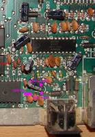
|
|
|
|
|
|
|
|
On my unit, the cap in that approximate position is c51, iirc. I gave it a shot last night and it didn't work either. :(
-Rob |
|
|
|
|
|
viletim!
|
|
You must have a board I've never seen before. My advice is to trace the audio track back from the pin on the A/V socket until you hit a capacitor. If that's too diffucult then just cut the track and intercept the audio right there. |
|
|
|
|
Ok. Well, which pin is the audio out? Is it pin 3? Or, to relieve confusion, does anyone have a pinout diagram? Also, I remember you said in your instructions to trace the audio pin on both output connectors back. Looks like there are 3 pins coming off the coax input. Which one is the correct one to trace from?
-Rob |
|
|
|
|
|
|
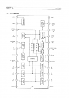
Here's a pinout diagram: http://gamesx.com/wiki/doku.php?id=av:genesisav I don't know what you are talking about in your next question.... The FM board should have the original (PSG) audio signal go into the red wire and the mixed (FM + PSG) audio will come out of the white wire. I think that most people would want this signal to gome out of the audio pin of the A/V socket. If you 'intercept' the audio further back in the audio signal path then you will get the dubious benifit of FM sound through the RF modulator too. |
|
|
|
|
|
|
In the installation instructions it says: "Trace the audio signal from both the RF modulator and A/V port (if there is one) until they meet at a common point. " So, did I misunderstand the instructions? I was just going by what you said to trace the signal back. -Rob |
|
|
|
|
|
|
|
Yes, all you need to do is find a capacitor that is on the same track as the audio pin of the A/V port and R/F modulator, remove the capacitor, then solder the ground to a ground point.
Look close by the A/V port, there will be a capacitor that you can use. (It will be an electrolytic if that helps) http://adelaideconcertband.org.au/sms1.jpg have a look at this pic to see if this is what your SMS 1 looks like, I had the same issue as you but I used the capacitor closest to the A/V port and it works a treat. Also SteveSMS is having some issues with his. |
|
|
|
|
Goto page Previous 1, 2, 3, 4, 5, 6 Next |