| Author |
Message |
- Joined: 06 Feb 2024
- Posts: 5
|
SMS2 PAL-G to NTSC help
 Posted: Tue Feb 06, 2024 5:04 pm Posted: Tue Feb 06, 2024 5:04 pm
|
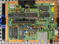
I recently purchased a PAL-G SMS 2 in rather pristine exterior and to some degree rather clean internals minus a lot of component repair required. I'll explain in a minute. I'm in the US and hoped to get it working and convert to NTSC. It was sold as no power as-is. I have a good handle on console repair (80s to current gen), soldering and rework skills so this particular one seemed a good challenge.
After opening the console, I found a ferrite bead/choke (FB7) rattling around inside. The leads on it were snapped off and unable to solder into the through holes. Otherwise, the console appeared very clean, though about a dozen or so component legs for various ceramic and axial capacitors, resistors, diodes were severed almost as if they'd snapped from the tension of the soldered through hole legs over time or just rotted away. There didn't seem to be any burn marks or burned components, just one of the legs not intact. I went about replacing all of them for exact spec components from this site's component list. The ferrite bead was reconstructed using similar/same gauge enameled copper wire and soldered back in.
Next, I decided the only way to test it was to NTSC mod it while the RF port was still in. Lifted pin 57 and grounded to pin 32 of IC5, lifted neg leg of R10 - tied to pin 6 of Z80, and then tied pin 7 of the CXA to pin 12. Crystal oscillator was was swapped for NTSC 53.693175. I didn't realize the cable ports are different than NTSC coax type so had to try using a composite cable with a component leg taped to it to probe the top leg of R21 to see if a raw composite video feed was shown. All I received was black screen. I changed channels to 36 (German PAL channel?) to see if it returned any image. Nothing. 7805 gives correct 9v in and 5v output. Looking for advice where to check next. Thanks in advance.
Edit: I have not changed any of the electrolytic capacitors yet though I do have replacements ready if necessary.
|
| |
 
|
- Joined: 05 Sep 2013
- Posts: 3828
- Location: Stockholm, Sweden
|
Posted: Wed Feb 07, 2024 9:01 am
|
NeoSnarl wrote All I received was black screen.
black screen likely means the VDP is outputting a black frame, can you check if the CPU is working?
|
| |

|
- Joined: 14 Aug 2000
- Posts: 742
- Location: Adelaide, Australia
|
SMS2 PAL-G to NTSC help
Posted: Wed Feb 07, 2024 10:17 am
|
You’re tapping CVideo before the 100uF decoupling capacitor (C38). You need to tap it after the capacitor. R21 may need to be changed to 75ohms for CVideo as well.
From your description, it sounds like the board was dropped or dragged against something and a number of components were sheared off. So there may be more damage to be found. Not gonna lie.
|
| |
|
- Joined: 06 Feb 2024
- Posts: 5
|
Posted: Sat Feb 10, 2024 2:23 pm
|
sverx wrote
black screen likely means the VDP is outputting a black frame, can you check if the CPU is working?
I took a look around and found another ceramic cap disconnected at C7 so will be replacing it. Don't have a scope or logic probe yet, I've been checking rough multimeter voltages on CPU pins 26 and 6 for Reset and clock. Clock is in the middle at 2.05v and reset stays low at about .5v before C7 disconnected and almost 0 after the leg of C7 completely separated. I also was tracing continuity on the reset circuit across the ICs and I can't seem to get continuity to Pin 26 of the cpu. Is that normal? Everywhere else on the board has continuity.
asynchronous wrote
From your description, it sounds like the board was dropped or dragged against something and a number of components were sheared off. So there may be more damage to be found. Not gonna lie.
Very well may be the case. It is super super clean, no dings, cracks, or abrasions on the motherboard or the shell (though that could just be a replacement).
|
| |
|
- Joined: 14 Aug 2000
- Posts: 742
- Location: Adelaide, Australia
|
SMS2 PAL-G to NTSC help
Posted: Sat Feb 10, 2024 4:53 pm
|
|
IC4 pin 46 is the source of the RESET signal. From there it goes to the CPU, IC5 and cartridge slot. On power-up, RESET should go to 5.0 volts after a split second delay and stay there. That’s definitely a problem on your board.
|
| |
|
- Joined: 06 Feb 2024
- Posts: 5
|
Posted: Mon Feb 12, 2024 12:39 am
|
IC4 Pin 46, C53, Cart pin 46, and IC5 Pin 23 show 5.02v on the reset circuit. C18, IC4 pin 47 show rising voltage from 3.6v to 4.96v over a couple seconds after powering on. Replaced C7 cap but that didn't change anything on IC1 Pin 26. Voltage fluctuates from near 0v to .5v.
Would it be out of the question to try a bodge wire from IC4 Pin 46 to IC1 Pin 26 since I can't find continuity? I'm not able to follow the trace from Z80 to IC4 pin 46 to see where I can find the break.
Are there other pin voltages that I should look at besides CLK? Address and Data? Would the reset circuit being held low prevent the correct readings on the other voltages?
|
| |
|
- Joined: 14 Aug 2000
- Posts: 742
- Location: Adelaide, Australia
|
SMS2 PAL-G to NTSC help
Posted: Mon Feb 12, 2024 3:13 am
|
Yes, you could try bridging a wire to the CPU reset pin. From what you have written it sounds like a broke track and not a short.
One way to confirm execution is to probe the /CE and /OE pins of the memory chips. These are pins 20 and 22 on 28-pin devices. But you should really confirm your power rails and reset circuit are stable at 5 volts first before that.
|
| |
|
- Joined: 06 Feb 2024
- Posts: 5
|
Posted: Mon Feb 12, 2024 3:31 am
|
asynchronous wrote One way to confirm execution is to probe the /CE and /OE pins of the memory chips. These are pins 20 and 22 on 28-pin devices. But you should really confirm your power rails and reset circuit are stable at 5 volts first before that.
Thanks. Just to confirm, probing of the /CE and /OE pins should happen before or after putting in the bridge wire?
|
| |
|
- Joined: 14 Aug 2000
- Posts: 742
- Location: Adelaide, Australia
|
Posted: Mon Feb 12, 2024 4:35 am
|
NeoSnarl wrote asynchronous wrote One way to confirm execution is to probe the /CE and /OE pins of the memory chips. These are pins 20 and 22 on 28-pin devices. But you should really confirm your power rails and reset circuit are stable at 5 volts first before that.
Thanks. Just to confirm, probing of the /CE and /OE pins should happen before or after putting in the bridge wire?
You need to fix the reset first. Otherwise the CPU will be held in reset.
|
| |
|
- Joined: 06 Feb 2024
- Posts: 5
|
Posted: Mon Feb 12, 2024 5:01 pm
|
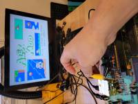
It's alive! Saving another broken console! Bridging IC4 pin 46 to IC1 Z80 pin 26 did the trick. Wasn't sure if the memory chips CE and OE pins were selected correctly but saw voltage ranges in the 2.5 -2.9v fluctuating. Tested with the rigged composite probe and got an image!
Thanks so much for your help!
|
| |
|