|
|
ForumsSega Master System / Mark III / Game GearSG-1000 / SC-3000 / SF-7000 / OMV |
Home - Forums - Games - Scans - Maps - Cheats - Credits Music - Videos - Development - Hacks - Translations - Homebrew |
View topic - GG ROM + BIOS + BURN QUESTION
 |
| Author | Message |
|---|---|
|
GG ROM + BIOS + BURN QUESTION
|
Guys I'm trying to make a GG card but strangely it doesn't start the game. the sum of the TMR is apparently correct. But I don't understand where the error is. SMS mapper cannot be used as a donor for GG?
|
|
|
|
|
|
|
|
Yes, it can be used. However you need to give more information to diagnose your error.
If your GG does not show a “produced by or under licence from” splash screen then it is not a header issue; if you do then you only need the TMR SEGA text. If this is read then you see the splash screen; if there is an issue reading it then the display stays blank. |
|
|
|
|
|
|
hello all beauty Maxim, so I'm from Brazil. here our suspicious GG tectoy it doesn't have bios because it starts directly on the sega screen of the original games, I'm trying to create a cart with mapper but I just tested a 32k rom without the mapper, connected directly to the CE ROM / MO7 BUS and the same screen was displayed. in blank [EDIT] I did a complete hardware check here and it is 100% correct. this leads me to believe that if our GG in Brazil does not have a BIOS. I have no more analysis options if our GAME GEAR doesn't have BIOS, the rom wouldn't need TMR this exhausts my options for something wrong in the cart |
|
|
|
|
|
Last edited by darleiv on Wed Jun 15, 2022 8:27 am; edited 2 times in total |
SCH
|
|
|
|
|
|
|
| Can you get an analyser on the cartridge bus to see the data going across it? My guess is that you aren’t getting good data on the data lines for whatever reason. | |
|
|
|
|
|
The 3v rom might be part of the problem? Are the address lines and control lines 5v tolerant? Level shifting the data lines back to 5v might also help. |
|
|
|
|
|
|
I don't have an oscilloscope. this error is a mystery. very strange |
|
|
|
|
|
|
I use the mx1610 that works at 5 volts I believe the problem is so simple that it goes unnoticed. schematic is not. rom header not sure. no problem in the GG. I have 5 units. I've tried everything =( 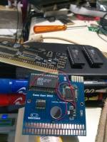
|
|
|
|
|
|
|
| Even a voltmeter on the lines should give you an indication if they are changing (0V for always 0, 5V for always 1, in between for changing values). If any of the data lines are always 0 or 1 it would explain a lot of what you see. Address lines are harder to diagnose but A0 should be very busy. | |
|
|
|
|
Last edited by wasup on Sun Jun 12, 2022 6:03 am; edited 1 time in total |
| How come the supply on the flash is 3v instead of 5v on the schematic? Does it still function properly at 3v even though its a 5v part? | |
|
|
|
|
|
|
I've only heard that using 3V ROMs on a console designed for 5V can be a bad thing. Like could cause overheating or something, I think?
I only remember reading a long time ago some article talking about beware of flash carts/"repros" that could be damaging to desirable vintage consoles. |
|
|
|
|
|
|
|
Shouldn't be a problem if done right, but in any case I think the 3v thing is a red herring here, from what I can tell from the photographs the ROM is powered from the 5v supply and looks like what I presume is a max3000 cpld is acting as a mapper and that is what the 3v supply is for. That device is 5v tolerant and the ROM is a 5v device.
Although not entirely clear, the op I think also implies that he has tried directly connecting the ROM to the gg bus without any mapper at all, and that didn't work either, so the problem appears to be more fundamental. @dar, from this and your other thread (did you ever get that working?), it's kind of hard to help with the small snippets of information you're giving each post. Perhaps you could take some time to explain *exactly* what steps you have gone through to test this, including the most basic experiment (sounds like this is trying to connect a ROM only with 15 bits (i.e. 32KB) directly to the gg bus? Tell us how you have implemented the address decoder and show us the connections you have made to the ROM. A completely accurate and clear schematic would be most helpful here if you are able to provide. Otherwise, if you are able to get a real gg game working with your console and you aren't able to get a 5v 32KB ROM with TMR header working then something *must* be wrong with the hardware itself or else with the flashing of the ROM. You should be able to easily discount header issues by testing with an emulator which enforces headers, iirc emulicious has an option for that but perhaps I'm misremembering. |
|
|
|
|
|
Last edited by darleiv on Wed Jun 15, 2022 8:28 am; edited 1 time in total |
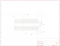
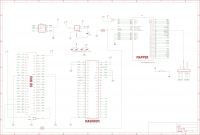
the 32k rom directly connect the CE rom to the Mo-7, you know if the CE of the GG is different from the SMS. and the RD that plays the role of the CE in the GG? I'm suspecting this. here is a sketch of the schematic. this is not a product but a prototype does the GG have any connection that differentiates it from the SMS? I suspect this is because I'm basing myself on the operation of an sms card to develop this prototype As for what you said about the header here in Brazil, GG doesn't have bios. and direct connection on the bus with 32k rom the HEADER is ignored and the game starts bypassing the bios , turning on the mO-7 
|
|
|
|
|
|
|
|
Sorry but your schematic makes very little sense.
What appears to be a ROM doesn't have a part label and the pinout doesn't seem to correspond to the MX29F1610 you say you're using. You say you're connecting CE to M0-7 but that is only one of 48 pins on the MX29F1610 so like I said without more precise information it is extremely difficult to help. |
|
|
|
|
|
|
sorry but the schematic is correct. when the pinout I used there are many alternative eproms like MX29F800 A29800 29F8000 and they all work the same as MX1610 changes 1 or 2 pins. then the eprom pinout would be irrelevant. since it is a test board, as for the project files I cannot make them available. because they are going to take and sell my mapper - my project is a non-commercial hobby the project is very clear because it has 3 parts. eprom slot mapper if you have trouble identifying which slot mapper or eprom is, send me a PM and I'll explain |
|
|
|
|
|
|
The GG connector has a pin that lets the cartridge choose whether to boot in native GG mode (with memory-mapped start button, stereo sound, 12bpp palette, 160x144) or SMS mode (with NMI start button, 6bpp palette, 240x192 scaled down) The 50-pin SMS connector has a bunch of pins that the GG doesn't (pin 4 = /MREQ, pins 34, 40-45, 48-50); the ones I haven't mentioned are also on the GG connector. The 45-pin GG connector has the LCD bias voltage (pin 1 = +34V), and digital inputs for the cart to select between GG/SMS, TV LCD passthrough, and external audio. See the four links in section "Game Media" on the wiki: https://www.smspower.org/Development/Pinouts-Index |
|
|
|
|