| Author |
Message |
- Joined: 01 Oct 2019
- Posts: 10
|
GameGear screen flicker after LCD swap.
 Posted: Tue Oct 01, 2019 8:43 am Posted: Tue Oct 01, 2019 8:43 am
|
I have a number of gamegears that I'm reviving, one of them appeared to work fine after a recap but the LCD was rotten. I replaced it with a good LCD from another GG and all seemed well. But a few minutes into a playing session the screen starts to flicker. It's as though somebody is turning the brightness up and down, but obviously nobody is.
(I CANT POST A LINK SO PLEASE SEARCH YOUTUBE FOR "gamegear screen flicker" - video uploaded just now)
Does anybody know anything about this sort of issue?
I have tried looking at the GG schematic (linked from Console5 website) but to be honest I don't understand the circuit.
The backlight itself is not flickering. It's definitely LCD brightness IMO.
I don't think it's the brightness potentiometer as I'd imagine that would cause the brightness to be stuck in one position rather than flicker like this. I could try stripping this GG down and spraying contact cleaner in there to see if it improves things. I'll do that tonight.
I have checked all the replacement caps and they're all the correct values in the right place and orientation. But does anybody know which caps control the brightness? I'd be interested in replacing those caps again to see what happens. I have a few spares so that's no problem.
I have checked the LCD contacts where I soldered the replacement LCD to the board and it all looks good to me, but I have no real way of knowing for sure. I assume they'e all good because there is nothing wrong with the picture aside from the brightness issues creeping in over time. Maybe I'll try reflowing all connections again, but I'd rather not risk that again unless I know it's a real possibility.
Does anybody know which specific pins on the LCD control brightness??
I have a few LCDs laying around and a few mainboards but as swapping them around is not without risk I'd rather leave that until I hit a dead end.
Does anyone have any ideas? Thanks.
|
| |
 
|
- Joined: 08 Sep 2018
- Posts: 270
|
Posted: Tue Oct 01, 2019 2:11 pm
|
|
It honestly sounds like a cap issue. Try re-flowing your caps or replacing the ones used to drive the LCD. Unfortunately I also do not know what caps do that but with a multi-meter you should be able to source it from the contrast dial easily.
|
| |
|
- Joined: 05 Nov 2014
- Posts: 435
- Location: Auckland - NZ
|
Posted: Tue Oct 01, 2019 8:20 pm
|
|
There will be something unstable somewhere thats causing that. If it still shows the same kind of thing after adjusting the contrast/brightness pot then try measuring the 34v pin on the power board and check if that is stable.. or just swap the power board for another and see if that helps. That 34v supply is only used for driving the lcd so my guess would be its in that part of the circuit somewhere.
|
| |
|
- Joined: 01 Oct 2019
- Posts: 10
|
Posted: Tue Oct 01, 2019 9:05 pm
|
thanks for your replies.
so I opened it up, checked all the replaced caps again, sprayed contact cleaner into the pot and adjusted that up and down for a while, and reflowed the solder contacts on the pot.
then tested the unit while it was open and its working fine now.
it'll be interesting you see whether it's still working properly once it's closed up again. I ran out of time so couldn't fo that tonight. will try tomorrow and let you know
|
| |
|
- Joined: 05 Nov 2014
- Posts: 435
- Location: Auckland - NZ
|
Posted: Tue Oct 01, 2019 9:13 pm
|
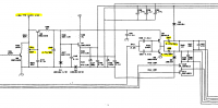
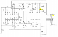
I just had a quick look at a VA1 schematic... its probably much the same on a VA0 i imagine. The attached snips show the caps i would check on the power supply and main board. Ive also highlighted the brightness pot for reference.
I expect that the LCD brightness in this situation is a function of its supply voltage rather than being controlled by a specific pin given the way the brightness pot is configured. The output of the pot is controlling that transistor next to it (in the schematic) forming a variable voltage regulator, so a dirty pot would definitely cause odd issues.
|
| |
|
- Joined: 01 Oct 2019
- Posts: 10
|
Posted: Wed Oct 02, 2019 7:45 am
|
Thanks for the added information Wasup!!
I have screwed the case back together this morning and left it running for about 5 minutes before I had to leave for work and it seemed ok, but I'll be more comfortable saying it's fixed after it's been running for an hour or so later today.
If there's still an issue I can focus on the caps you suggested and I'm sure this info will be useful to others too!
|
| |
|
- Joined: 01 Oct 2019
- Posts: 10
|
Posted: Wed Oct 02, 2019 8:06 pm
|
|
damn it still flickers. I'll need to check the caps you mentioned and then as a last resort change the lcd onto a different board.
|
| |
|
- Joined: 01 Oct 2019
- Posts: 10
|
Posted: Fri Oct 04, 2019 6:33 am
|
|
so I checked all the caps mentioned previously and they were fine. I found through trial and error that the lcd only flickers when the security screw behind the cartridge is tightened. interesting...
|
| |
|
- Joined: 01 Oct 2019
- Posts: 10
|
Posted: Mon Oct 07, 2019 5:05 pm
|
|
I traced this to a cap on the audio board. when the security screw was tightened a cap would be pressed by the case and one leg would short against a surface mount cap. I insulated one from the other with tape and the problem is solved!
|
| |
|
- Joined: 08 Sep 2018
- Posts: 270
|
Posted: Mon Oct 07, 2019 5:35 pm
|
|
That is awesome! Glad to hear you got it fixed!
|
| |
|