|
|
ForumsSega Master System / Mark III / Game GearSG-1000 / SC-3000 / SF-7000 / OMV |
Home - Forums - Games - Scans - Maps - Cheats - Credits Music - Videos - Development - Hacks - Translations - Homebrew |
View topic - Help with rare SMS revision. Buttons auto press even without a controller plugged in
 |
| Author | Message |
|---|---|
|
Help with rare SMS revision. Buttons auto press even without a controller plugged in
|
|
Hello
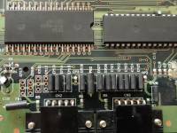
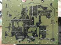
I have a SMS III Compact with a rare motherboard revision, TecToy Cod. 199.002.511.814. it is mostly similar to a Pal SMS2 171-5922 console, so I've been using that service manual as a reference. My current issue is that the second I turn the console on, sonic instantly loads, he jumps straight up into the air, then he lands and ducks and stays that way as if down button is stuck. I don't know what to do but here is what I have tried so far Checked voltage of the pins on controller ports 1 and 2. There was 0v on pins 1, 2, and 6 (up, down, and TL). I checked continuity on the EMI filters caps, and similarly had issues with em16 (TL), em11 (up), and em12 (down). Specifically for 1 up and down the issue was there was no path to ground on the em filters between the outside legs and the middle leg (as all other caps had), and the issue for TL is that it seemed short circuited, so I lifted the leg out of circuit (pin 14 is TL on IC4 315-5237). Even with the leg lifted out of the motherboard, it beeps when I do continuity test to ground, and I don't think this should be happening I checked all capacitors and they seem correct. I don't know how to test the ferrite beads but they all have continuity from one side to the other. I reflowed all the pins on the controller socket and all ICs using flux on the existing solder. I tested for bridging between controller pins, and between legs of the IC, and the EMI but didn't see any bridging Is there anything else I can check? I'm fairly new to troubleshooting like this. I didn't even know what am EMI was until last night 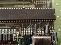

|
|
|
|
|
|
|
| Usually it's those EMI caps. But it's quite possible the IC that leads to that (sorry don't remember the part number) is now faulty. | |
|
|
|
|
|
It does all this even when no controllers are plugged in you mean? Then it certainly means there's a short on the board - which might not be easy at all to be located... |
|
|
|
|
|
|
Continuity between ground and what - the now lifted leg of pin 14 or the now empty pad that received it? If the former, then it's almost certainly a fault with IC4 - others have reported similar in the past. If the latter, and if you are testing with no controller inserted, then using SMS2 schematics as a guide then that should indeed not be possible, even with a faulty cap or bead. Possibilities in this case are (potentially new) solder bridge, conductive debris bridge, some kind of serious mechanical damage shorting two nearby tracks, or some short within the D sub connector itself. |
|
|
|
|
|
|
|
The EMI filters are a pi filter consisting of a series inductor and two capacitors to ground that form a low pass filter. With the device removed from the board, you should read continuity between the 2 outer pins and no shorts between an outer pin and the inner pin.
Assuming you’re right about no bad traces, with the EMI filters removed from the board, and the console power on, the IO pins on the IC should read close to 5 volts. If they don’t, then you have a faulty IC. A good test is to plug in a Mega Drive 6-button joypad and see if this gets rid of the issue. If it does, there’s a chance that adding external pull-up resistors to fault pins may fix the issue. |
|
|
|
|
|
|
|
After further testing it ended up being a bad IC
I was testing with a 6button controller but it didn't make a difference Basically with the bad leg lifted completely out of socket i tested continuity from the TL leg to ground and it was 0.001 resistance |
|
|
|
|
|
|
Yeah, the lifted leg to the ground on the same chip beeps. It measures 0.001 resistance. I've accepted that the IC is fried. |
|
|
|
|
|
|
| You might as well give the discrete pull-up resistor fix a try before you give up all hope. It might not work, but it's much quicker to try it than lifting the chip. | |
|
|
|
|
|
Ok. Do you have any details on how I would do that? How many ohm resistors? Do in just jump it from VCC to the lifted pin? Since the pin is shorted to ground, do i risk any other damage by using the pull up resistor? I'm pretty new to all of this type of repair work and I'm a novice with electronics. Everything you see above I learned how to do in the last 1 week |
|
|
|
|
|
|
Sure, no worries, I know it can feel a bit intimidating to go to work with a soldering iron on your precious hardware but if you're methodical and patient it's not so hard. I guess your alternative if you want to save the hardware is to replace the chip, which is straightforward in principle but is quite a serious job and the risk there is damaging some PCB tracks so if you like I would suggest trying a single pullup first, to see if it fixes one of the control signals. If it doesn't then you know the only option is replacing the chip. If it does then you can maybe try another and another one by one. If this does feel like too much, you ought to be able to find somewhere that can repair your unit for you, depending on where you live. Of course they will charge for it, but then you will have some assurance that they have done similar repairs in the past :) The general idea with the pullups is to bridge each failing pin with a resistor between that pin and the positive supply, and the end result should look something like this picture I found online, but note this is a different device (actually a Megadrive / Genesis) and so not the same pins you want, it's just for illustration: https://imgur.com/mHzs8OM I think that pin 48 of IC4 should be your positive supply voltage, so for example if you wanted to try this for 1TL on pin 14 you would bridge pin 14 and pin 48 with a resistor. You'd need to reconnect pin 14 to the PCB first of course, now that it's already disconnected, either by putting the pin back in the pad, or with a little jumper wire or even with the leg of the resistor. You can verify that pin 48 is the correct pin by checking continuity between that pin and any other known points that should be the positive supply. If that works (i.e. if you test the system and that button is fixed), and you wanted to try a second resistor, you could solder one leg of it to the next pin you wanted to try, and then solder the other leg to the leg of the first resistor that's connected to pin 48 – you don't need to try and solder everything directly to pin 48 as that might get really crowded and difficult to manage – you can use the leg of the first resistor. If you solder far enough away from pin 48 on the resistor leg, it shouldn't re-melt the solder on pin 48 which is always a real pain when trying to connect multiple things to the same point! Just make very sure that you don't touch the "control pin" legs of the resistors to anything else. Only the legs connected to pin 48 should be touching / connected together. Remember that you will need to get the case down after you've finished your repairs, so you should try and make everything as neat and as compact as possible. In terms of soldering technique, it's a bit of an acquired skill, but you could try trimming and bending the pins of the resistor into position before you solder it, then use a little masking tape, kapton tape or blu-tack to secure it in position onto the body of the chip so you don't burn your fingers trying to hold it. It might be helpful to put a little blob of solder onto the two IC pins before you position the resistor, that way you can reflow the blob once the resistor is in position. Once one of the legs is tacked in place with solder, dealing with the second leg becomes easier. Something like 10k ohm is a common value to use in this situation, but the exact value isn't hugely important. The resistor in the photo linked above looks like a 0.25W resistor to me, which is probably a decent choice here because they are physically a little smaller than 0.5W resistors which are maybe a little more commonly available to casual hobbyists, but from an electrical point of view any power rating will do really – you are sinking a tiny amount of current through it anyway. It's unlikely you'll cause any further damage to the chip or the rest of the system by connecting a resistor between positive supply and those pins. Because something like 10k is a relatively high resistance, even if you have a hard short to ground on those pins, only a small current will flow between Vcc and GND (around half a milliamp) and there are other pull-ups and current paths in your system which do the same thing already. Just check and re-check your work with a multimeter after you've finished soldering and before turning the supply back on, to make sure that you've not accidentally created any shorts in unintended places. After doing any work like this I usually check to make sure I haven't created a short across the power supply, and also usually check adjacent pins to make sure I haven't accidentally bridged them. If all this feels like too much, as I said you can probably find somewhere to repair your system for you! |
|
|
|
|
|
|
|
Thank you.
I gave this a try and it didn't help I tried lower and lower resistance values until I was all the way down to 10ohms and at that point it pulled the whole system voltage down low enough the console wouldn't power on I also tried it with 5v to the connector using the resistor and that for 5v to the pin on the controller connector but still had issues. And trying to put the resistor on both the IC side and the controller side had the same results as when I only tried on the IC side. I also tried running the 5v from alternative points such as directly from the power regulator and same results. Basically if I did a voltage test to the pin on the IC, with any resistor value from 47ohms to 10k resulted in no more than 0.08 volts. With 10ohm as I said it pulled the whole 5v rail down to like 1v I also tried a diode, thinking that would prevent it from pulling the full 5v rail down, but it didn't work like that. I am going to order a junk for repair system and hope the IC is good in that device, and install DIN socket to make it easier to add and remove if it doesn't work. I really appreciate the help you provided |
|
|
|
|
|
|
Ah, sorry it didn't work out :(
Yep, sounds like a plan. Good idea with the socket - again just make sure that the case will close with a socketed IC but I'm sure there will be plenty of room.
Yes unsurprising there, that's putting an extra half an amp across the power supply which is a chunk! Your resistor must have surely gotten pretty hot doing that! I wouldn't advise going anywhere near that low in future experiments 😅
Well best of luck with it... If you do finally manage to get it working would be lovely to hear back. |
|
|
|
|
|
|
|
You can use a replacement for the 315-5237 chip, I have reversed it and made the gerbers and jed files available:
https://www.smspower.org/forums/19719-3155216And3155237IOChipsReproductionsAlsoL... |
|
|
|
|
|
|
| I just got a junk donor system. So this weekend I'll test the chip I need from that system. Then I'm just waiting on the dip sockets before I do much else. If I'm lucky the sockets will get here before the weekend | |
|
|
|
|
|
Whoa. That's probably over my head because over never heard of Jed files before and ive only sent off for a pcb once before. I'll read through the post now, but I just got a donor board which hopefully has a working 315-5237 in it. If not, well your clone will probably be real helpful then. I think it's worth it for this quite rare system, plus I'll feel really good if I actually fix this thing because it's taught me a lot so far |
|
|
|
|
|
|
| Anyone happen to know what size dip socket I need for 315-5237? The ones I ordered just arrived and they are way too small | |
|
|
|
|
|
Too small how? Should be 2.54mm pitch (0.1"), 15.24mm width (0.6") and 48 pins total (double-checked using Apocalypse's gerbers for verification) |
|
|
|
|
|
|
|
Thanks. I didn't know how to measure and ordered something smaller than that. It was 2 inches long total for biggest size.
I can probably skip the socket. Just worried if it kills the new chip. So I'll order up a 2.54 row of headers unless you know the name of the socket. I can't find any actual sockets this size |
|
|
|
|
|
|
It's the simplest way to go. Personally I'd worry less about killing the chip and more what are you going to do if the scavenged chip is also faulty - 48 more DIP pins to desolder!
Here's an example from Mouser of a socket that should fit. If you can't find 48 pin sockets where you are based, you could also see whether you can find 24 pin sockets and try mounting them next to each other. Just make sure they are 0.6" (15.24mm) row spacing. But yes, you could also order some strips of 2.54mm IC sockets, like this kind of thing to suit. PCB pin header sockets of the kind that are commonly used in hobby electronics, if that's what you are suggesting, might not work if they are too tall and of the sprung type so I'd say purpose designed IC sockets or pin sockets are best. |
|
|
|
|
|
|
| Thank you for the links. I'll order what you sent | |
|
|
|
|
|
|
It's fixed! Thanks so much for all the help
After removing the 315-5237 I confirmed the short is gone and then put in the socket and booted it up and it was working! Sonic didn't auto start, jump, and duck. Only remaining issue was the pause button didn't work properly. I tried to remove the silicone and clean the contacts but couldn't get rubber back in. So I popped in a clicky button in its place and now it's all working. Next step is to do the region mod and 50/60hz. I tried removing the 000ohm resistor at jp3 and without it the system didn't boot. With jp2 set or unset there was no difference. With jp2 set, jp2 didn't have any effect. I cut the trace between jp2 and jp3 and tried again, but same thing. At best all it would do it boot to a black and white checker screen or a green screen. So I put the jp3 back in place and bridged jp2 and 3 back together. So I'm not sure what the jumpers are but I couldn't get them to do anything for me. I know on genesis there are 4 sets of jumpers and some traces to cut but I don't think these line up with those |
|
|
|
|