|
|
ForumsSega Master System / Mark III / Game GearSG-1000 / SC-3000 / SF-7000 / OMV |
Home - Forums - Games - Scans - Maps - Cheats - Credits Music - Videos - Development - Hacks - Translations - Homebrew |
View topic - SMS region hack
 |
| Author | Message |
|---|---|
|
SMS region hack
|
|
So on master system, unlike Megadrive the only region hack is not a good idea.
Do you reckon you could make this check fail without grounding that pin? Would a PWM of certain frequency injected in the pin do it you reckon ? Sick of waiting for shit to come from China! Waiting on PIC chips to attempt to have them inject the 'stack setup' bytes on the bus for games that need it for to add to cartridge adapter and tinker with a new pause mod but feel like playing with the guts of an SMS. Been a while. Maybe a multi BIOS down the track Someone give me a project idea lol 😃 |
|
|
|
|
|
SMS region hack
|
|
The KILLGA pin can also be used for a Region Mod.
It's discussed here: https://www.smspower.org/forums/13127-DisablingTheIOChip?highlight=killga You'll be struggling to pull KILLGA to disable the chip in time before the I/O write to $3F takes effect, but pulling KILLGA for the subsequent I/O read of $DD apparently works. |
|
|
|
|
|
|
|
You reckon there's anyway to muffle the I/O read without injecting voltage or grounding a pin that shouldn't be grounded?
Also man, just wondering if you know where the page that raph refers to on his "setting up the stack" page has gone. It's a dead link. I want to rewrite it in C++ for a nano and get a better understanding of it without doing a shit tonne of research prior... Then I can come with a PIC version to add to SMS adapters that don't have stack set up. https://www.raphnet.net/programmation/md_sms_stack/index_en.php I just want a quick tinker without lots of 'book work'. I've had enough of data sheets for now. |
|
|
|
|
|
|
|
https://web.archive.org/web/20190403192608/http://www.smspower.org/forums/14084-...
Found it |
|
|
|
|
|
Last edited by L10N37 on Sun Sep 19, 2021 8:56 am; edited 2 times in total |
|
This is Raphnets "stack setup code" rewritten for an Arduino Nano
// Stack pointer initilisation for after-market Master System cartridge adapters on Megadrive / Genesis // Used Information from SMS power and Raphnet // Vajskids Consoles 2021 #define wait_() while (bitRead (PINB, 3) == 0) {;} // wait for RD high again #define wait() while (bitRead (PINB, 3) == 1) {;} // wait for RD low pulse void setup() { // all outputs for bits 0:5 DDRD = 0B11111100; // all outputs except RD/CLK pin as input, bits 6/7 not usable (mapped to xtal) DDRB = 0B00110111; //CE HIGH bitWrite (PORTB, 4, 1); // Setup first byte port B bits bitClear (PORTB, 0); bitClear (PORTB, 1); //Serial.begin (115200); } void complete() { //Serial.println (" PWR DOWN "); complete(); } void loop() { wait() // present Initial byte and keep CE high //Serial.println (" Byte 1"); //delay (500); PORTD = 0x84; //delay (500); wait_(); //byte 2 wait(); //Serial.println (" Byte 2"); //delay (500); PORTD = 0X4; //delay (500); wait_(); //byte 3 wait(); //Serial.println (" Byte 3"); //delay (500); bitWrite(PORTD, 7, 1); bitWrite (PORTB, 0, 1); bitWrite (PORTB, 1, 1); //delay (500); wait_(); //byte 4 wait(); //Serial.println (" Byte 4"); //delay (500); bitClear (PORTB, 0); bitClear (PORTB, 1); PORTD = 0x94; //delay (500); wait_(); //byte 5 wait(); //Serial.println (" Byte 5"); //delay (500); bitWrite (PORTB, 0, 1); bitWrite (PORTB, 1, 1); PORTD = 0xE4; //delay (500); wait_(); //byte 6 wait(); //Serial.println (" Byte 6"); //delay (500); PORTD = 0x1C; //delay (500); wait_(); //Serial.println (" FINISHED "); // high-z everything DDRB = 0x00; DDRD = 0x00; PORTD = 0x00; PORTB = 0x00; // Serial.println (" HIGH-Z "); // finished complete(); } /* D9/PB1 to D7 D8/PB0 to D6 D7/PD7 to D5 D6/PD6 to D4 D5/PD5 to D3 D4/PD4 to D2 D3/PD3 to D1 Arduino D2/PD2 to D0 SMS 0x21 | 00100001 0x01 | 00000001 0xE1 | 11100001 0x25 | 00100101 0xF9 | 11111001 0xC7 | 11000111 */ |
|
|
|
|
|
|
|
Something i was playing with, but havnt had much luck with so far, was to build some hardware that sits between the cart and the console. The hardware can read the cart data in real time and either pass it straight through to the console unaltered or alter it to make the region check fail.
By looking for a write to port $3f, you could then alter it to something like port $dc, as writes to that port have no effect, and the output pins on controller ports would not change state. That should then make it think its a JP system. You need the z80 m1 pin to reference the reads against though so you can make sure your looking at opcode reads and not other stored data. Im not sure if that pin is included on the megadrive in sms mode though, so this may not be a viable solution. |
|
|
|
|
|
|
I played about with a slightly different approach to this method a while ago and managed to stop the write happening. Worked really well too. Itll only work on an sms though as its using a few of the z80 pins which arent brought out on a game gear or megadrive.. plus a game gear or megadrive dont have a KILLGA pin either https://www.smspower.org/forums/17533-RegionChangingInHardware |
|
|
|
|
|
|
|
@wasup
sounds like a good project for a little FPGA like the one on the old SMS everdrives. I will check that out. Doesn't need it for MD as they have an easy region switch. My code above doesn't seem to work, i switched out the cart slot. Now my adapter isn't working at all, but MD games are fine. Not sure what I've broken, i checked all the bits with a meter on each pin through each read pulse, so when it was low the correct byte was present for all 6. I did have a bit missing in setup which i've added, and I wrote the wrong bit high for CE which I've fixed... Sort of a mixed post, just trying to get the stack set then I will check out the region stuff. I figured with the arduino being 8mhz it shouldn't matter that the bits weren't all set in one line of code per byte. Edit: Fixed the code, its working perfect. If you have an output written high, then switch it to input it becomes 'INPUT_PULLUP' I've fixed it and repasted - will come in handy for people with aftermarket SMS adapter |
|
|
|
|
|
|
|
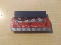
Bit of a hack, need to make a new board that slots the arduino in with the header pins but I'll probably never get around to it. I have a refurbished gamegear here that i was meant to make a new audio board for, all the parts are here, lost interest.
There's these little class D amps i wanted to try out that should use less power that i've used in other projects before unfortunately this doesn't fix R-type but i think lidnariq has a hack for that, It usually works if you load a megadrive game first. Had it loading sequentially time after time earlier. Also the resistor shouldn't be needed if you just turn D12 into a pulled up input 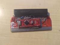
|
|
|
|
|
|
|
According to my understanding, to fix R-Type, you would need to arrange for bit 4 at RAM address $C000 to be zero, otherwise a later write to port 3E based on the initial value of $C000 may disable RAM, depending on what $C000 happened to hold. Before the final RST $0 (C7) instruction, you could add code to do this. If D0 was not wired to a pull-up it would be easy... LD A,$A8 LD ($C000),A (3E A8 32 00 C0) But assuming you kept my setup with D0 wired to a pull-up (or IO pin with pull-up) it gets more interesting, all opcodes and values must have bit zero set.. I'm not a Z80 expert, a shorter sequence could probably be created, but here is something I think could work. ; Load A9 in A
21 A9 A9 LD HL,$A9A9 7D LD A,L ; Load $C000 in HL 21 01 C1 LD HL,$C101 25 DEC H 2D DEC L ; Write A (A9) to C000 77 LD (HL),A After 77 you would have to let go of the data bus for 1 cycle to avoid contention while the CPU writes to RAM. Then grab it again for one cycle to drive the final RST $0. |
|
|
|
|
|
|
Thanks for info Raph I will have to make a new board so the nano can slot into it. Recently, lost some files that will take quite a bit of time to reproduce (a perfectly manicured, beveled edge famicom cart connector, identical to factory with the very outer fingers a little wider) as there were mistakes on rev1. Every track needed to go through a via to the opposite side of the board (facepalm), otherwise all good. Hopefully these ones are intact on the buntu lappy. I did read your webpage about Sega's method and only having access to a 7bit wide BUS, therefore, having to use instructions that all had LSB set high. I didn't do this though on that code above though, it's just written high on a separate GPIO pin for every transmission. **Anyway, its 1am and 2 litres of pepsi max was consumed today so don't mind all the bad grammar and typos and stuff :) |
|
|
|
|