|
|
ForumsSega Master System / Mark III / Game GearSG-1000 / SC-3000 / SF-7000 / OMV |
Home - Forums - Games - Scans - Maps - Cheats - Credits Music - Videos - Development - Hacks - Translations - Homebrew |
View topic - TMS9929A video output levels
 |
| Author | Message |
|---|---|
|
TMS9929A video output levels
|
|
Today I measured out the output levels of TMS9929ANL in my SC-3000.
+----------------+------+------+------+
| | Y | R-Y | B-Y | +----------------+------+------+------+ | 1 Black | 0 | 0 | 0 | | 2 Medium green | 520 | -384 | -256 | | 3 Light green | 648 | -288 | -192 | | 4 Dark blue | 392 | -60 | 516 | | 5 Light blue | 520 | -32 | 456 | | 6 Dark red | 456 | 354 | -160 | | 7 Cyan | 712 | -452 | 228 | | 8 Medium red | 520 | 452 | -192 | | 9 Light red | 648 | 452 | -192 | | A Dark yellow | 712 | 96 | -384 | | B Light yellow | 780 | 96 | -288 | | C Dark green | 456 | -320 | -220 | | D Magenta | 520 | 260 | 196 | | E Grey | 780 | 0 | 0 | | F White | 964 | 0 | 0 | +----------------+------+------+------+ All the levels are in millivolts. For color signals 0V is black level. I have tried to do RGB conversion and I've got red and blue values to be pretty close to other documentation but I have not managed to find a way to get green color work out. G-Y = a * (R-Y) - b * (B-Y) R = Y + (R-Y) G = Y - (G-Y) B = Y + (B-Y) I have found various numbers for the "a" and "b" but I never get output that looks what I see on TV, yellows are most noticably off. Any idea what they're supposed to be ? |
|
|
|
|
|
|
I do not know about this particular IC, but I had noticed in other ICs like BA6592F which you need equalizing R-Y and B-Y to same levels before converting them to RGB. Eg BA6592F B-Y 0.42vpp and R-Y 0.55vpp |
|
|
|
|
|
|
|
I was doing the conversion "digitally", to derive 8bit RGB levels that one would use in emulation, though I do want to do analog conversion too sometime.
I found a document about interfacing the TMS to various monitors and it does look like B-Y is scaled compared to R-Y, and reasoning was to get most saturated colors over most accurate conversion, so that tells me you aren't supposed to do a perfect conversion. Yet somehow the TV does things that way, and you do get correct looking colors. I'll figure it out :P |
|
|
|
|
|
|
Thanks for posting the voltage table. From a quick look that is pretty close to readings I have taken. ie. overall the voltage levels are reasonably close to the spec in the TMS9929A manual (there is of course a DC offset on those voltages). I have included the voltage table from the manual below for interest.
These are the calculations I was playing around with a few years back when trying to solve the colour balance problem for component video output. It shows the RGB values used by MESS (pulled from the source code) and the scaled transformations used to derive them. Well, more or less. It is a little confused, and there are some mistakes. And I was focused on YPbPr, not RGB :) But you might find it useful to look at my calculations around those MESS RGB values. http://www.classic-computers.org.nz/forums/viewtopic.php?f=11&t=960&star... And this is one of the excellent references I used. I think this has most of your answers regarding transformations between colour spaces complete with comments about colour choices for digital. http://www.poynton.com/notes/colour_and_gamma/ColorFAQ.html I hope those help :) Slightly off topic, but if you do the real analog conversion, you need some extra black magic to get the colour balance correct on a TMS9929A. I've finally built a component video circuit that gives great output from the TMS9929A on my SC-3000 with good reds, blues, yellows, and greens. I haven't built a RGB output circuit from it, but here is what you need to get perfect Y/Pb/Pr output from a TMS9929A. 1. Scale the 1.44v p-p output from all three channels (0.44v for sync and 1v for Vblack to Vwhite) from the TMS9929A to 1v p-p (0.3v for sync and 0.7v for Vblack to Vwhite). So scale all three channels by 0.694. 2. In addition to that, scale B-Y by 0.564 and R-Y by 0.713 (as per ITU Rec 601) to give Pb and Pr So you scale the TMS9929A Y by 0.694, B-Y by 0.694 * 0.564 = 0.391, and R-Y by 0.694 * 0.713 = 0.495, or reasonably close to these figures. (Actually, you also need another scale factor of two in there because you should be driving your output through a 75ohm resistor, which then acts as a voltage divider with the 75ohm termination to ground in your TV to drop everything back again). 3. Final black magic - get rid of the evil pulses that the TI engineers inserted into the back porch of the R-Y and B-Y signals to mark the color burst interval. If you don't, then your TV will read the incorrect Vnocolor level for Pb and Pr on every single line and your colour balance will always be wrong. (Note - TMS9929A only. TMS9928A does not have back porch pulses). You can do this either by: 1. a sample-hold circuit by sampling Vnocolor on B-Y or R-Y during the horizontal sync pulse and then playing it back during the back porch burst interval (hackaday solution - see below) 2. averaging B-Y and R-Y together during the back porch burst interval (my solution). This works because the pulses are the same amplitude but opposite phase so they cancel back to Vnocolor if you average them together. There is a good Hackaday project that solved the TMS9929A sync pulse problem and explains it better than I have above. (Note that TMS9928A does not have pulses on back porch). They use a different technique with a sample / hold on the B-Y voltage level during the CSYNC pulse (when B-Y is still at Vnocolor) which is then played back during the burst interval. I tried that myself and it works well. The 'averaging' approach I used is just me putting my spin on it :) Different solution to the same problem. https://hackaday.io/project/13056-tms9929a-rgb-and-component-adapter Download the hackaday board layout zip and take a look at the schematic they have used if you are interested. It is for MSX, but it does both RGB and Y / R-Y / B-Y output, so you can work out the mixing levels they used for RGB. I've attached a draft pdf of my component video daughter board schematic for reference showing the R-Y and B-Y averaging. That works great on the breadboard. I will draw up an Eagle PCB for it when I have time. Cheers 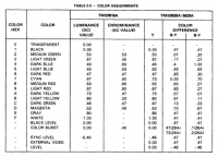
|
|
|
|
|
|
|
|
A couple more useful links for your colour conversions and scale factors to use.
http://www.equasys.de/colorconversion.html http://www.equasys.de/colorformat.html The RGB to YPbPr colour conversion for SDTV matrix on the above page is identical to what I used in my draft component daughterboard schematic once you apply that 0.564 scalar to B-Y to give Pb and 0.713 scalar to R-Y to give Pr. (This is also consistent with Charles Poynton's notes in point 28. How do I encode Y'PBPR components?). ie. Y = 0.299 R + 0.587G + 0.114B Pb = -0.169R - 0.331G + 0.500B Pr = 0.500R - 0.419G - 0.081B The inverse matrix they show there for SDTV is: R = Y + 0Pb + 1.402Pr G = Y - 0.344Pb - 0.714Pr B = Y - 1.772Pb + 0Pr or, if you substitute Pb = 0.564R-Y and Pr = 0.713Pr then you get R = Y + 0B-Y + R-Y G = Y - 0.194B-Y - 0.509R-Y B = Y + B-Y + 0R-Y
So... to answer your question about the correct value for 'a' and 'b' for SDTV, it looks like a = 0.509 and b = 0.194. If that doesn't give you the result you want then I think your question around which scalars to use is really about choosing a specific colour space you need RGB for as the scalars differ depending on your choice. If you use the above scalars, the result looks great on a SDTV because the TV is using the Rec 601 colour space. That will also work fine on a modern HDTV because the TV is smart enough to know that the SDTV signal uses a different colour space to an HDTV signal and it will adjust the colour balance accordingly. However if you use those exact same RGB values on a computer monitor (say in Photoshop by just painting a block of colours for a test pattern) it will probably look different because the computer monitor and your operating system / paint program / image viewer are calibrated for a different colour space. I assume that MESS has colour correction built in for this to display the correct colour space. And that seems a reasonable assumption in general - regardless of the values that you choose for RGB encoding, you need to specify the colour space to use when displaying it. And for an emulator of a TMS9929A, ITU Rec 601 appears to be the correct colour space to use for display. Or perhaps using YCbCr solves that issue for choosing colours for emulation as that is designed for digital video. I'm not sure - I haven't looked at YCbCr in detail as it wasn't directly relevant to my analog project. I think :) That sounds about right anyway. Cheers |
|
|
|
|
|
|
|
For YPbPr you got to scale the R-Y and B-Y signals by some amount, the technical reason for that was to boost SNR for transmission and that's why you needed the extra scale factors to get component out work nice, and to get the conversions presented in the pages to work also.
I am aware of the color pulses in porches and how they can botch up stuff, I like your idea to solving it, though not totally sure about the implementation, it doesn't look super elegant but if it works, naiss :P In the hackaday RGB converter R-Y is boosted by a small amount (or Y is reduced in relation to R-Y), and the photo of TV does show correct yellows so it is doing things right on that regard. Looking at the schematic this is going on there : R = Y + (R-Y*a)
B = Y + B-Y G = (Y*b) - ((R-Y*c) + (B-Y*d)) "TMS99xx interface to color monitors" does a similar thing, except it scales B-Y rather than R-Y compared to previous. It is almost like they do kind of conversion to YPbPr and then that to RGB. RGB converter board in SC-3000 manual does something like : R = Y + R-Y
B = Y + B-Y G = (Y*a) - ((R-Y*b) + (B-Y*c)) I have not seen what the result is supposed to be like, but I cannot imagine it being very different from what composhit or RF looks like on those machines. Interestingly it does nothing about the pulses in porch area... ---- R = Y + 0B-Y + R-Y
G = Y - 0.194B-Y - 0.509R-Y B = Y + B-Y + 0R-Y That didn't result in correct output either, yellows in particular were off as with all other values I've found and tried. It is certain one has to scale the R-Y and/or B-Y signals prior (or do other magic later as the SC-3000 RGB module). YCbCr is a different beast altogether, I see no advantages of using it as it is essentially incompatible due to totally different luma coeffs anyway. Thänk you for all the info, your thread on the other forum is very interesting too ~ |
|
|
|
|
|
|
No worries, I hope some of that was helpful.
I have attached a photo a friend of mine took a few years back. This is from his Yeno SC-3000 which has the RGB daughterboard. This is Congo Bongo output to a Philips CM8833-II monitor. He got very clear, bright colours. I tried my RGB Yeno on a couple of TVs a few years back (it is packed away under the stairs now). I have a horrible 20" CRT Goldstar with a SCART port which it worked with. I didn't love the colour balance from memory (I seem to recall it was a little dull), and the TV display curved badly at the edges. But the output was very good on correctly displaying different coloured text with different background colours (on composite, the text bleeds so badly that you can't even read it with some color combinations). So provided you get a good TV that works with it, the output can be very good. Much much better than composite and possibly better than my breadboard component mod. The problem I had was I didn't have a good quality TV that worked with both RGB and component, so I couldn't do back to back testing against the component video mod for performance against a test pattern.
Thanks :) I wasn't 100% sure on the implementation either so I shuffled it around on the breadboard and took measurements with my Rigol scope until it worked consistently. I learned a lot as I went along. I still have a couple of question marks but I can't actually seem to improve the performance any further, so I think it is good enough as it is. It seems to be pretty reliable but I need to try it with some more TVs. It sounds like many newer TVs may not support 240p over component. Good luck finding the correct coefficients for your RGB calculation. 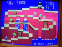
|
|
|
|
|