| Author |
Message |
- Joined: 01 Jan 2005
- Posts: 360
- Location: Stockholm, Sweden
|
Adaptateur RVB
 Posted: Tue Mar 25, 2008 9:31 pm Posted: Tue Mar 25, 2008 9:31 pm
|
|
While in Paris, I saw a man selling Sega machines on a fleamarket. Apart from Megadrives and MS controllers, he had a box labeled "adaptateur R.V.B." with two leads, one going into the DIN AV connector on a Megadrive or Powerbase, and the other with a SCART connector. I found this curious since I have a fully working SCART cable without a big box in the middle. Am I right in presuming that this adaptor turns RGB into composite SECAM for old TVs without RGB?
|
| |
  
|
- Site Admin
- Joined: 19 Oct 1999
- Posts: 14738
- Location: London
|
Posted: Wed Mar 26, 2008 7:44 am
|
|
It is just a SCART lead. RVB is French for RGB. I think the huge box just contains the necessary resistors.
|
| |
|
- Joined: 20 Oct 2007
- Posts: 35
- Location: France - Marseille
|
Posted: Mon Mar 31, 2008 12:08 pm
|
adaptateur is a friend : it means adaptator.
R.V.B. is for Rouge Vert Bleu ;) (for general knowledge)
|
| |
|
|
OpaKidd
|
Posted: Tue Apr 29, 2008 10:56 am
|
idrougge wrote While in Paris, I saw a man selling Sega machines on a fleamarket. Apart from Megadrives and MS controllers, he had a box labeled "adaptateur R.V.B." with two leads, one going into the DIN AV connector on a Megadrive or Powerbase, and the other with a SCART connector. I found this curious since I have a fully working SCART cable without a big box in the middle. Am I right in presuming that this adaptor turns RGB into composite SECAM for old TVs without RGB?
You are right! I had that kind of cable. The box makes a color correction for (very) old french TV sets.
|
| |
|
- Site Admin
- Joined: 19 Oct 1999
- Posts: 14738
- Location: London
|
Posted: Sun May 04, 2008 5:51 pm
|
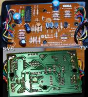
Here's a couple of photos of the guts of the Adapteur RVB. Would anyone care to figure out what it's doing?
[edit: forum attachment thumbnails seem to be broken...]
|
| |
|
- Joined: 01 Jan 2005
- Posts: 360
- Location: Stockholm, Sweden
|
Posted: Sun May 04, 2008 11:31 pm
|
|
I'd wager it supplies the correct voltage to put the TV in RGB mode and adjust the RGB values, but that doesn't seem to entirely make sense.
|
| |
|
- Joined: 19 Dec 2005
- Posts: 34
- Location: United Kingdom
|
Posted: Wed May 14, 2008 5:19 pm
|
The TL497ACN is a Texas Instruments 500mA Peak Step-Up, Step-Down, Inverting switching regulator. It is, as idrougge says, to generate the voltage to cause the TV to switch into RGB mode - pin 8 of an S-VHS SCART socket is sometimes known as "Remote Control". The voltage on this pin causes the appliance to automajically switch over to the RGB signals.
Knowing which pins are connected in each connector and being able to read the cable identifiers on the board would be helpful. To trace the circuit fully I will also need to know the transistor markings.
Regards
Marty
|
| |
|
- Site Admin
- Joined: 19 Oct 1999
- Posts: 14738
- Location: London
|
Posted: Wed May 14, 2008 5:53 pm
|
|
I had trouble getting a photo without a flash reflection. If you're really interested I'll open it up again.
|
| |
|
- Joined: 19 Dec 2005
- Posts: 34
- Location: United Kingdom
|
Posted: Tue May 20, 2008 7:14 pm
|
Quote If you're really interested I'll open it up again.
I can think of more interesting things to do! Thanks anyway, but no thank you!
Regards
Marty
|
| |
|
|
viletim!
|
Posted: Wed May 21, 2008 5:14 am
|
Using a dedicated switching regulator has to the most unimaginative way to generate the SCART switching voltage (it only needs to source 1.2mA for christ sake!).
Marty,
The video amp is a textbook example of an emitter follower amplifier. The transistor be any generic NPN with a pinout of base, collector, emitter (left to right).
|
| |
|
- Joined: 11 Aug 2007
- Posts: 87
- Location: Coimbra, Portugal
|
Posted: Sun Aug 31, 2008 1:59 pm
|
viletim! wrote Using a dedicated switching regulator has to the most unimaginative way to generate the SCART switching voltage (it only needs to source 1.2mA for christ sake!).
The scart's pin 8 (Function select) is being set at a potential between 9.5 and 12 V = AV Mode.
From wikipedia:
Quote 8 - Status & Aspect Ratio [0-0.4V → off, 5-8V → 16:9, 9.5-12V → on/4:3]
So it uses an boost converter. (It could be going to the input DC terminal, connected to the 7805, but you can't guarantee it's average voltage.)
I think it's a very interesting solution, and quite compact.
Maxim, if you could tell me the wire's functions and transistor models, I could easily reverse engineer the circuit. This is what I came up now.
|
| |
|