|
|
DevelopmentSega Master System / Mark III / Game Gear |
Home - Forums - Games - Scans - Maps - Cheats - Credits |
YM 2413 Reverse Engineering Notes 2015 - 12 - 24
by andete. Original documents available at: https://github.com/andete/ym2413/tree/master/results
<< YM2413 Reverse Engineering Notes 2015-12-16 | YM2413 Reverse Engineering Notes | YM2413 Reverse Engineering Notes 2015-12-31 >>
Last time we walked over all registers and indicated some features that haven't been investigated yet. In this post I'll investigate two of those features: sustain level (SL) and key scale rate (KSR).
Sustain level (SL)
The level of the sustain phase in the ADSR envelopes is controlled by two 4-bit fields (bits 7-4 in registers R#6 and R#7), one for the modulator and one for the carrier operator. According to the YM2413 application manual, those bits select a sustain level between 0dB and 45dB (in steps of 3dB). Let's verify this. I measured with the following settings:
| Operator | AM | PM | EG | KR | ML | KL | TL | WF | FB | AR | DR | SL | RR |
|---|---|---|---|---|---|---|---|---|---|---|---|---|---|
| modulator | 0 | 0 | 1 | 0 | 00 | 0 | 63 | 0 | 0 | 15 | 00 | 00 | 15 |
| carrier | 0 | 0 | 1 | 0 | 00 | 0 | 0 | 04 | 07 | nn | 07 |
| reg#0x20 = 0x00 | key-off |
| reg#0x10 = 0x80 | fnum=0x180 |
| reg#0x30 = 0x00 | max volume / custom instrument |
| reg#0x20 = 0x1B | key-on / block=5 |
I varied the car.SL field between 0..15. I used a fairly high frequency so that the waveform has plenty of peaks in each envelope-step. This way the shape of the envelope is clearly visible. The results:
| +0 | +1 | +2 | +3 | ||
| 0 | 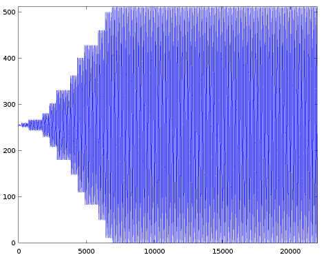 |  |  |  | |
| 4 |  |  |  |  | |
| 8 |  |  |  |  | |
| 12 |  | 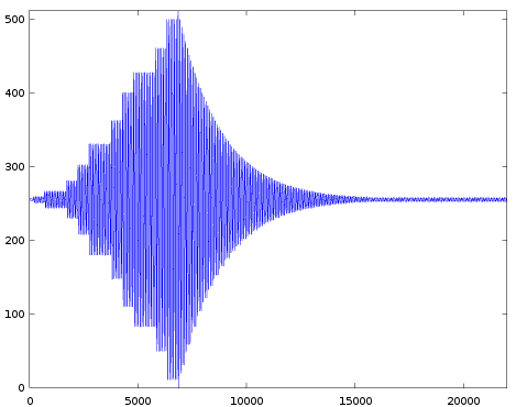 |  |  |
For SL=0 there is no decay at all. For higher SL values the decay stops at higher attenuation levels (=lower amplitude). I looked in more detail at the amplitude for each of these levels and translated that to an internal envelope level. (From earlier results we know the internal envelope level is a value between 0..127. We also know the maximum amplitude for each envelope level.) I also converted that envelope level to a dB-value (each envelope step corresponds to 0.375dB). The results are shown in the next table:
   SL | EG-level | dB
  ----+----------+----
    0 |     0    |  0
    1 |     8    |  3
    2 |    16    |  6
    3 |    24    |  9
    4 |    32    | 12
    5 |    40    | 15
    6 |    48    | 18
    7 |    56    | 21
    8 |    64    | 24
    9 |    72    | 27
   10 |    80    | 30
   11 |    88    | 33
   12 |    96    | 36
   13 |   104    | 39
   14 |   112    | 42
   15 |   120    | 45
These results are not very surprising. It's also not very surprising that these are the exact same amplitudes as for the volume setting, because this is also a 4-bit value that controls attenuation in steps of 3dB.
I was wondering whether very fast decay rates would get clipped at the requested sustain level or stop (right) past it (without clipping). A related question: does the hardware use an equality comparison (only stop at exactly the requested level) or a more expensive less-than comparison (stop at any level higher than the requested level)?
A quick recap about the decay rates: For slow-to-normal decay rates the envelope level is increased by only 1 step every so many samples (powers of 2). By only taking steps of 1 it's not possible to skip over the destination level. But for fast decay rates the envelope level is increased by 1 or 2 steps every sample.
So I tried to setup a test where the envelope level is increased by 2 and would skip over the requested sustain level. However it turns out that every time the level is increased by 2, the level is at an even number. So it will always exactly land on the requested sustain level (multiples of 8). In other words: I was unable to setup an experiment that can answer the above questions.
UPDATE: right before posting this I thought of the following experiment: Maybe it's possible to change the DR setting while the decay phase is already active. If done at just the right time (e.g. at an odd envelope level) it might be possible to make the decay skip over the target envelope level. I'll try this later (possibly this experiment requires small extensions to the ARM code running on my test board).
Key scale rate (KSR)
This feature is also well explained in the YM2413 application manual. The operator's attack, decay and release rates can be set via 3 4-bit values (located in registers R#06 an R#07). Though these settings only partly determine the actual rate. The manual gives the following formula for the effective rate:
RATE = 4 * R + Rks
with R: the 4 bit 'AR', 'DR', "RR' selected rate (instrument settings) Rks: the value from the table below and RATE is clipped at [0..63]
  BLOCK ||   0   |   1   |   2   |   3   |   4   |   5   |   6   |   7   |
  FNUM8 || 0 | 1 | 0 | 1 | 0 | 1 | 0 | 1 | 0 | 1 | 0 | 1 | 0 | 1 | 0 | 1 |
  ------++---+---+---+---+---+---+---+---+---+---+---+---+---+---+---+---+
  KSR=0 || 0 | 0 | 0 | 0 | 1 | 1 | 1 | 1 | 2 | 2 | 2 | 2 | 3 | 3 | 3 | 3 |
  KSR=1 || 0 | 1 | 2 | 3 | 4 | 5 | 6 | 7 | 8 | 9 | 10| 11| 12| 13| 14| 15|
Or another way to look at this table:
- For KSR=0, the value of Rks is formed by the 2 MSB bits of BLOCK
- For KSR=1, Rks is the concatenation of the (3 bit) BLOCK value with the MSB bit of FNUM.
So the key-scale feature gives higher frequency notes higher (=faster) attack-, decay- and release-rates. And the KSR bit controls how big this effect is.
The description of the KSR feature is fairly clear. Nevertheless I'd like to verify it. These are the measurement settings I used:
| Operator | AM | PM | EG | KR | ML | KL | TL | WF | FB | AR | DR | SL | RR |
|---|---|---|---|---|---|---|---|---|---|---|---|---|---|
| modulator | 0 | 0 | 1 | 0 | 00 | 0 | 63 | 0 | 0 | 15 | 00 | 00 | 15 |
| carrier | 0 | 0 | 1 | x | xx | 0 | 0 | 15 | xx | 15 | 07 |
- DR, KR, BLOCK and FNUM are varied as part of the experiment.
- ML is varied (usually 8 or 15) to have enough oscillations per
- envelope step to be able to see the peaks in the amplitude.
I'll explain the results with an example. For these settings
DR=4 KSR=0 BLOCK=4 FNUM8=0 (measurement 'a' from the table below)
I obtained this waveform:
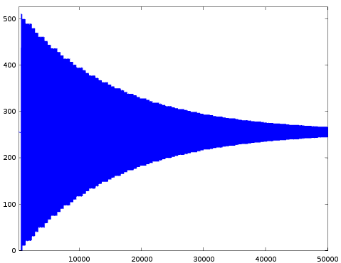

So as expected we get a waveform that rapidly rises to maximal amplitude (AR=15) and then slowly decays (DR=4). If we zoom in we can figure out the effective rate that was used:
In the zoomed image we see wide and narrow steps in this pattern:
wide, narrow, narrow, wide, narrow, narrow, ...
From an earlier post we know this pattern occurs when the lower two bits of the effective rate are '0b10'. Looking at the X-axis we see that a narrow step takes 512 samples (we know it must be a power of 2). From that we can calculate the upper 4 bits as
13 - log2(512) = 4
Combining both gives an effective rate of 4*4+2 = 18. And this is also
the rate obtained via the formula 'RATE = 4 * R + Rks' for these
settings.
I manually verified several different settings. First I tried all different settings that would would give an effective rate of 18 according to the formula. These are all combinations I could think of:
        RATE = 4 * R + Rks
    a)   18  = 4 * 4 +  2    R=4  KSR=0  BLOCK=4  FNUM8=0     confirmed
    b)   18  = 4 * 4 +  2    R=4  KSR=0  BLOCK=4  FNUM8=1     confirmed
    c)   18  = 4 * 4 +  2    R=4  KSR=1  BLOCK=1  FNUM8=0     confirmed
    d)   18  = 4 * 3 +  6    R=3  KSR=1  BLOCK=3  FNUM8=0     confirmed
    e)   18  = 4 * 2 + 10    R=2  KSR=1  BLOCK=5  FNUM8=0     confirmed
I verified that I indeed get the expected waveform for all these.
I also tried several variations on the above settings. The formula predicts other effective rates for these variations, and I can confirm that each time the measured rate matches those predictions.
    f)   25  = 4 * 4 +  9    R=4  KSR=1  BLOCK=4  FNUM8=1     confirmed
    g)   24  = 4 * 4 +  8    R=4  KSR=1  BLOCK=4  FNUM8=0     confirmed
    h)   22  = 4 * 4 +  6    R=4  KSR=1  BLOCK=3  FNUM8=0     confirmed
    i)   22  = 4 * 3 + 10    R=3  KSR=1  BLOCK=5  FNUM8=0     confirmed
    j)   10  = 4 * 2 +  2    R=2  KSR=0  BLOCK=5  FNUM8=0     confirmed
Next steps
The two topics above are probably not the most interesting. The measurements simply match the fairly good description in the YM2413 application manual.
I actually wanted to include a 3rd topic in this post about the transition between the attack and decay phase (e.g. how long does the envelope remain at maximum amplitude when the attack phase ends and the decay phase starts). But investigating this is taking longer than I expected. So I decided to postpone this topic to a later post.
The transitions between the other envelope states (damp-attack, decay-sustain, sustain-release) might follow after. There are also still a few bits left in the registers that haven't been investigated yet.
<< YM2413 Reverse Engineering Notes 2015-12-16 | YM2413 Reverse Engineering Notes | YM2413 Reverse Engineering Notes 2015-12-31 >>
