|
|
DevelopmentSega Master System / Mark III / Game Gear |
Home - Forums - Games - Scans - Maps - Cheats - Credits |
Light Phaser

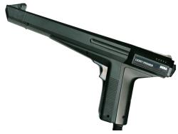
Master System Light phaser
(code 3050)
Overview
The Light Phaser is the Master System's light gun accessory. It consists of a light sensor in the tip of the gun, which is focussed on a small area of the screen; and a trigger which corresponds to joypad button 1. When the trigger is pulled, the game flashes the screen in a way that is detectable by the light sensor, and hardware built in to the console allows the game to determine where the gun is pointing.
Schematics
Light Phaser schematic by furrtek
Connections
The device attaches to either controller port:
| Pin | Function | Wire Colour |
|---|---|---|
| Up | Not connected | N/A |
| Down | Not connected | N/A |
| Left | Not connected | N/A |
| Right | Not connected | N/A |
| VCC | VCC | Green |
| TL | Trigger | Blue |
| TH | Light sensor | White |
| GND | Ground | Black |
| TR | Not connected | N/A |
The TL and TH lines are configured as inputs.
Because the controller ports are active-low, a 1 in the corresponding port register signifies "not pressed" or "dark", and a 0 "pressed" or "light". This is achieved in hardware by leaving lines unconnected when inactive, and connecting them to Gnd when active.
Technical details
When the software detects that the trigger has been pressed (typically at the start of the VBlank), it makes sure to display the next frame of video as a solid, reasonably bright colour. This can be done by any method, but probably the easiest is to set all palette entries to the chosen colour.
During this frame, a busy loop should poll the joypad TH line (bit 6/7 of port $DD for player 1/2 respectively). When it is read as active (0), the television raster has reached part of the screen "visible" to the light sensor.
When this is detected, it is possible to read the scanline counter to determine the Y position, and the HCounter to determine the X position. The latter is a special case - the system hardware is designed so that the HCounter is automatically latched when either controller's TH line is active (0), and cannot be freely read. Without this, there would be timing difficulties in getting an accurate X position solely from software.
These X,Y coordinates are stored to memory and the polling process continues until the end of the current framelight sensor registers darkness again (TH line reads 1), indicating that the television raster has passed the sensor's visible area for the current scanline. It is not possible to record the X coordinate of this "right edge" transition because it does not latch the HCounter hardware. The polling routine then resets to the initial state, waiting for the high-to-low transition for the next scanline, which may or may not be detected by the light sensor.
Because the sensor "sees" a circular portion of the screen, and not a single pixel, the X,Y coordinates detected in this fashion define some part, or all, of the left boundary of the sensor's "seen" circle. These coordinates are then processed in a suitable fashion to try to determine (possibly not to a great level of accuracy) the X,Y coordinates of the centre of the circle, which corresponds to the screen position pointed at by the gun.
The polling can either stop when it determines that enough data has been found (perhaps, no lightgun response for 2 scanlines), or the end of the active display area has been reached (typically, scanline 192).
Official Sega documentation states:
"...it is advisable to do some sort of averaging and extrapolation to arrive at a center position of the scanned circle."
A simplistic algorithm might be to find the minimum X coordinate detected, and the minimum Y coordinate detected; these should correspond to the left and top of the circle respectively. Thus, their respective Y and X coordinates should give the circle's centre. Of course, in practice the data will be more noisy and unreliable.

