Sega Genesis Technical Manual - YM2612 section
Many years ago, there was a file called SEGA2.DOC which was a Mega Drive technical manual with a bunch of errors and some file corruption. A bit less long ago, a bunch of scans surfaced which seemed to exactly match, including a lot of hand-written parts corresponding to the more extreme errors; I transcribed and corrected the errors on this page.
More recently, some better scans of the same manual, but in better quality without all the errors and some slightly different wording, appeared. I've updated this page with those scans and their pagination. Pages are numbered and hyperlinked for your convenience. Shading indicates additions/corrections/comments.
Contents
- Overview
- A little bit about operators
- Register overview
- Envelope specification
- Part I memory map
- The registers
- Register 22H - LFO
- Registers 24H & 25H - Timer A
- Register 26H - Timer B
- Register 27H - Timers; Ch3/6 mode
- Register 28H - Key on/off
- Registers 2AH & 2BH - DAC
- Register 30H+ - detune; multiple
- Register 40H+ - total level
- Register 50H+ - rate scaling; attack rate
- Register 60H+ - first decay rate; amplitude modulation
- Register 70H+ - secondary decay rate
- Register 80H+ - secondary amplitude; release rate
- Register 90H+ - proprietary
- Registers A0H-AFH+ - frequency
- Register B0H+ - feedback; algorithm
- Test program
Original page numbers
4 - 5 - 6 - 7 - 8 - 9 - 10 - 11 - 12 - 13 - 14 - 15 - 16 - 17
Overview
The Yamaha 2612 Frequency Modulation (FM) sound synthesis IC resembles the Yamaha 2151 (used in Sega's coin-op machines) and the chips used in Yamaha's synthesizers.
Its capabilities include:
- 6 channels of FM sound
- An 8-bit Digitized Audio channel (as replacement for one of the FM channels)
- Stereo output capability
- One LFO (low frequency oscillator) to distort the FM sounds
- 2 timers, for use by software
To define these terms more carefully: an FM channel is capable of expressing, with a high degree of realism, a single note in almost any instrument's voice. Chords are generally created by using multiple FM channels.
The standard FM channels each have a single overall frequency and data for how to turn this frequency into the complex final wave form (the voice). This conversion process uses four dedicated channel components called 'operators', each possessing a frequency (a variant of the overall frequency), an envelope, and the capability to modulate its input using the frequency and envelope. The operator frequencies are offsets of integral multiples of the overall frequency.
There are two sets of three FM channels, named channels 1 to 3 and 4 to 6 respectively. Channels 3 and 6, the last in each set, have the capability to use a totally separate frequency for each operator rather than offsets of integral multiples. This works well (l believe) for percussion instruments, which have harmonics at odd multiples such as 1.4 or 1.7 of the fundamental.
The 8-bit Digitized Audio exists as a replacement of FM channel 6, meaning that turning on the DAC turns off FM channel 6. Unfortunately, all timing must be done by software -- meaning that unless the software has been very cleverly constructed, it is impossible to use any of the FM channels at the same time as the DAC. As you probably know, loads of games actually do this.
Stereo output capability means that any of the sounds, FM or DAC, may be directed to the left, the right, or both outputs. The stereo is output only through the headphone jack.
The LFO, or Low Frequency Oscillator, allows for amplitude and/or frequency distortions of the FM sounds. Each channel elects the degree to which it will be distorted by the LFO, if at all. This could be used, for example, in a guitar solo.
Finally, the system has two software timers, which may be used as an alternative to the Z80 VBLANK interrupt. Unfortunately, these timers do not cause interrupts - they must be read by the software to determine if they have finished counting.
A little bit about operators
There are four dedicated operators assigned to every channel, with the following properties:
- An operator has an input, a frequency and envelope with which to modify the input, and an output.
- The operators have two types, those whose outputs feed into another operator, and those that are summed to form the final wave form. The latter are called "slots".
- The slots may be independently enabled, though Sega's software always enables or disables them all simultaneously.
- Operator 1 may feed back into itself, resulting in a more complex waveform.
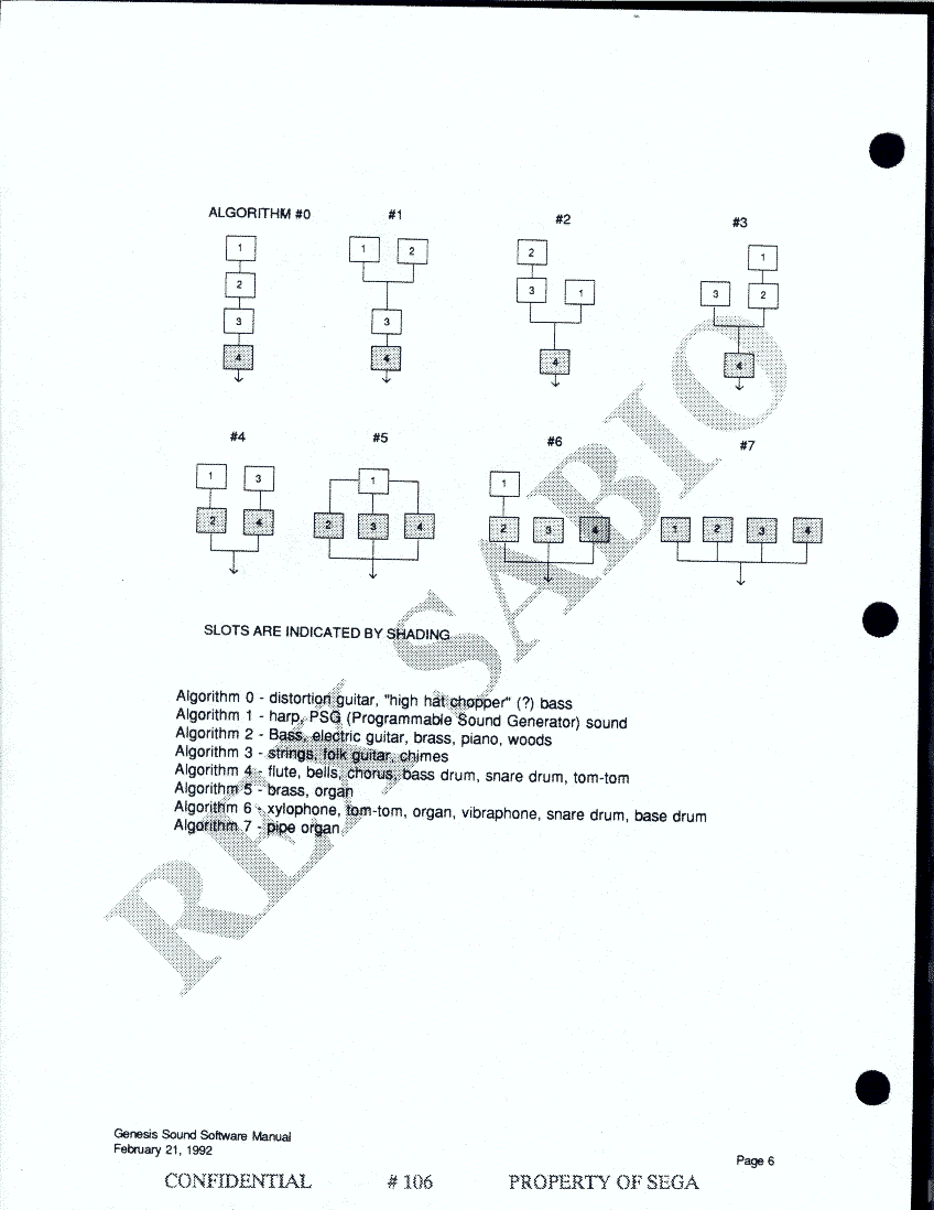
These operators may be arranged in eight different configurations, called "algorithms". Following is a diagram of the algorithms.
| Algorithm # | Layout | Suggested uses |
| 0 | 
| Distortion guitar, "high hat chopper" (?) bass |
| 1 | 
| Harp, PSG (programmable sound generator) sound |
| 2 | 
| Bass, electric guitar, brass, piano, woods |
| 3 | 
| Strings, folk guitar, chimes |
| 4 | 
| Flute, bells, chorus, bass drum, snare drum, tom-tom |
| 5 | 
| Brass, organ |
| 6 | 
| Xylophone, tom-tom, organ, vibraphone, snare drum, base drum |
| 7 | 
| Pipe organ |
Slots are indicated by shading.
Register overview
The system is controlled by means of a large number of registers. General system registers are:
- timer values and status, software use
- LFO enable and frequency, to distort the FM channels
- DAC enable and amplitude
- output enables for each of the 6 FM channels
- number of frequencies to be used in FM channels 3 and 6
Usually, an FM channel has only one overall frequency, but if so elected, FM channels 3 and 6 use four separate frequencies, one for each operator.
The remainder of the registers apply to a single FM channel, or to an operator in that channel. Registers that refer to the channel as a whole are:
- frequency number (in the standard case)
- algorithm number
- extent of self-feedback in operator 1
- output type, to L, R, or both speakers. This can only be heard if headphones are used.
- the extent to which the channel is distorted by the LFO.
Registers that refer to each operator make up the remainder. The four operator's connections are determined by the algorithm used, but the envelope is always specified individually for each operator. In the case of FM channels 3 and 6, the frequency may be specified individually for each operator.
Envelope specification
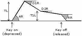
The sound starts when the key is depressed, a process called 'key on'. The sound has an attack, a strong primary decay, followed by a slow secondary decay. The sound continues this secondary decay until the key is released, a process called 'key off'. The sound then begins a rapid final decay, representing for example a piano note after the key has been released and the damper has come down on the strings.
The envelope is represented by the above amplitudes and angles, and a few supplementary registers. Used in the above diagram are:
| TL | Total level, the highest amplitude of the waveform. |
| AR | Attack rate, the angle of initial amplitude increase. This can be made very steep if desired. The problem with slow attack rates is that if the notes are short, the release (called 'key off') occurs before the note has reached a reasonable level. |
| D1R | The angle of initial amplitude decrease. |
| T1L | The amplitude at which the slower amplitude decrease starts. |
| D2R | The angle of secondary amplitude decrease. This will continue indefinitely unless 'key off' occurs. |
| RR | The final angle of amplitude decrease, after 'key off'. |
Additional registers are:
| RS | Rate scaling, the degree to which envelopes become shorter as frequencies become higher. For example, high notes on a piano fade much more quickly than low notes. |
| AM | Amplitude Modulation enable, whether or not this operator will allow itself to be modified by the LFO. Changing the amplitude of the slots (those colored gray in the diagram on page 3) changes the loudness of the note; changing the amplitude of the other operators changes its flavor. |
| SSG-EG | A proprietary register whose usage is unknown. It should be set to 0. |
The YM-2612 may be accessed from either the 68000 or the Z80. In both cases, however, the bus is only 8 bits wide.
The YM-2612 is accessed through memory locations 4000H - 4003H in the Z80 case, or A04000H - A04003H in the 68000 case. These will be referred to as 4000 to 4003.
The internal registers of the FM-2612 are divided as follows:
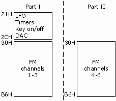
To write to Part I, write the 8 bit address to 4000 and the data to 4001. To write to Part II, write the 8-bit address to 4002 and the data to 4003.
CAUTION: Before writing, read from any address to determine if the YM-2612 I/O is still busy from the last write. Delay until bit 7 returns to 0.
CAUTION: in the case of registers that are "ganged together" to form a longer number, for example the 10-bit Timer A value or the 14-bit frequencies, write the high register first.
READ DATA: Reading from any of the four locations gives:
| D7 | D6 | D5 | D4 | D3 | D2 | D1 | D0 |
| Busy | Overflow A | Overflow B | |||||
| Busy | 1 if busy, 0 if ready for new data |
| Overflow | 1 if the timer has counted up and overflowed. See register 27H. |
Part I memory map
| D7 | D6 | D5 | D4 | D3 | D2 | D1 | D0 | |
| 22H | LFO enable | LFO frequency | ||||||
| 24H | Timer A MSBs | |||||||
| 25H | Timer A LSBs | |||||||
| 26H | Timer B | |||||||
| 27H | Ch3 mode | Reset B | Reset A | Enable B | Enable A | Load B | Load A | |
| 28H | Operator | Channel | ||||||
| 29H | ||||||||
| 2AH | DAC | |||||||
| 2BH | DAC en | |||||||
| 30H+ | DT1 | MUL | ||||||
| 40H+ | TL | |||||||
| 50H+ | RS | AR | ||||||
| 60H+ | AM | D1R | ||||||
| 70H+ | D2R | |||||||
| 80H+ | D1L | RR | ||||||
| 90H+ | SSG-EG | |||||||
| A0H+ | Frequency number LSB | |||||||
| A4H+ | Block | Frequency Number MSB | ||||||
| A8H+ | Ch3 supplementary frequency number | |||||||
| ACH+ | Ch3 supplementary block | Ch3 supplementary frequency number | ||||||
| B0H+ | Feedback | Algorithm | ||||||
| B4H+ | L | R | AMS | FMS | ||||
Each of 30H-90H has twelve entries, three channels × four operators:
| 30H | Ch 1 op 1 |
| 31H | Ch 2 op 1 |
| 32H | Ch 3 op 1 |
| 33H | |
| 34H | Ch 1 op 2 |
| 35H | Ch 2 op 2 |
| 36H | Ch 3 op 2 |
| 37H | |
| 38H | Ch 1 op 3 |
| 39H | Ch 2 op 3 |
| 3AH | Ch 3 op 3 |
| 3BH | |
| 3CH | Ch 1 op 4 |
| 3DH | Ch 2 op 4 |
| 3EH | Ch 3 op 4 |
| 3FH |
Channels 1-3 become channels 4-6 in Part II.
Each of A0H-B4H has three entries. All follow the pattern:
| A0H | Ch 1 |
| A1H | Ch 2 |
| A2H | Ch 3 |
| A3H |
with the exception that A8H and ACH follow the pattern:
| A8H | Ch 3 op 2 |
| A9H | Ch 3 op 3 |
| AAH | Ch 3 op 4 |
| ABH |
"Part II" is a duplication of 30H - B4H, where channels 1-3 are replaced by 4-6.
The registers
Register 22H - LFO
| D7 | D6 | D5 | D4 | D3 | D2 | D1 | D0 | |
| 22H | LFO enable | LFO frequency | ||||||
| LFO enable | 1 is enabled, 0 is disabled. | |||||||
| LFO frequency /Hz | 0 | 1 | 2 | 3 | 4 | 5 | 6 | 7 |
| 3.98 | 5.56 | 6.02 | 6.37 | 6.88 | 9.63 | 48.1 | 72.2 | |
The LFO (Low frequency Oscillator) is used to distort the FM sounds' amplitude and phase. It is triply enabled, as there is:
- A global enable in register 22H
- A sensitivity enable on a channel by channel basis, in registers B4H-B6H.
- An amplitude enable on an operation by operation basis, in registers 60H-6EH.
If the LFO is desired, enable it by register 22H. Next, select which channels will be affected by the LFO, to what degree, and whether their amplitude or frequency is affected, by setting registers B4-B6H. Finally. if a channel's amplitude is affected, make sure that it is only the "slots" that are affected by setting registers 60H - 6EH.
Registers 24H & 25H - Timer A
| D7 | D6 | D5 | D4 | D3 | D2 | D1 | D0 | |
| 24H | Timer A MSBs | |||||||
| 25H | Timer A LSBs | |||||||
Registers 24H and 25H are ganged together to form 10-bit Timer A, with register 25H containing the least significant bits. They should be set in the order 24H, 25H. The timer lasts:
- 18 × (1024 - Timer A) microseconds
Timer A = all 1's -> 18 µs = 0.018 ms
Timer A = all 0's -> 18,400 µs = 18.4 ms
Register 26H - Timer B
| D7 | D6 | D5 | D4 | D3 | D2 | D1 | D0 | |
| 26H | Timer B | |||||||
8 Bit Timer B lasts:
- 288 × (256 - Timer B ) microseconds
Timer B = all 1's -> 0.288 ms
Timer B = all 0's -> 73.44 ms
Register 27H - Timers; Ch3/6 mode
| D7 | D6 | D5 | D4 | D3 | D2 | D1 | D0 | |
| 27H | Ch3 mode | Reset B | Reset A | Enable B | Enable A | Load B | Load A | |
Register 27H controls the software timers and the Channel 3 (and 6) mode, two entirely separate items.
| Ch3 mode | D7 | D6 | Description |
| Normal | 0 | 0 | Channel 3 is the same as the others |
| Special | 0 | 1 | Channel 3 has 4 separate frequencies |
| Illegal | 1 | 0 | |
| 1 | 1 |
A normal channel's operators use offsets of integral multiples of a single frequency. In special mode, each operator has an entirely separate frequency. Channel 3 operator 1's frequency is in registers A2 and A6. Operators 2 to 4 are in registers A8 and AC, A9 and AD, and AA and AE respectively.
No one at Sega has used the timer feature, but the Japanese manual says:
| Load | 1 starts the timer, 0 stops it. |
| Enable | 1 causes timer overflow to set the read register flag. 0 means the timer keeps cycling without setting the flag. |
| Reset | Writing a 1 clears the read register flag, writing a 0 has no effect. |
Register 28H - Key on/off
| D7 | D6 | D5 | D4 | D3 | D2 | D1 | D0 | |
| 28H | Operator | Channel | ||||||
| 4 | 3 | 2 | 1 | |||||
This register is used for "Key on" and "Key off". "Key on" is the depression of the synthesizer key, "Key off" is its release. The sequence of operations is: set parameters, Key on, wait, key off. When key off occurs, the FM channel stops its slow decline and starts the rapid decline specified by "RR", the release rate.
In a single write to register 28H, one sets the status of all operators for a single channel. Sega always sets them to the same value, on (1) or off (0). Using a special channel 3, I believe it is possible to have each operator be a separate note, so there is possible justification for turning then on and off separately.
| D2 | D1 | D0 | Channel |
| 0 | 0 | 0 | 1 |
| 0 | 0 | 1 | 2 |
| 0 | 1 | 0 | 3 |
| 1 | 0 | 0 | 4 |
| 1 | 0 | 1 | 5 |
| 1 | 1 | 0 | 6 |
Registers 2AH & 2BH - DAC
| D7 | D6 | D5 | D4 | D3 | D2 | D1 | D0 | |
| 2AH | DAC | |||||||
| 2BH | DAC en | |||||||
Register 2AH contains 8 bit DAC data.
If the DAC enable is 1, the DAC data is output as a replacement for channel 6. The only Channel 6 register that affects the DAC is the stereo output portion of register B4H.
Registers 30H - 90H are all single-operator registers. Please see page 8 for how the twelve channel-operator combinations are arranged.
Register 30H+ - detune & multiple
| D7 | D6 | D5 | D4 | D3 | D2 | D1 | D0 | |
| 30H+ | DT1 | MUL | ||||||
Both DT1 (detune) and MUL (multiple) relate the operator's frequency to the overall frequency.
MUL ranges from 0 to 15 (decimal), and multiplies the overall frequency, with the exception that 0 results in multiplication by 1/2. That is, MUL=0 to 15 gives ×1/2, ×1, ×2, ... ×15.
DT1 gives small variations from the overall frequency × MUL. The MSB of DT1 is a primitive sign bit, and the two LSB's are magnitude bits. See the next page for a diagram.
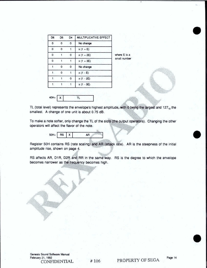
| D6 | D5 | D4 | Multiplicative effect |
| 0 | 0 | 0 | No change |
| 0 | 0 | 1 | ×(1+ε) |
| 0 | 1 | 0 | ×(1+2ε) |
| 0 | 1 | 1 | ×(1+3ε) |
| 1 | 0 | 0 | No change |
| 1 | 0 | 1 | ×(1-ε) |
| 1 | 1 | 0 | ×(1-2ε) |
| 1 | 1 | 1 | ×(1-3ε) |
where ε is a small number.
Register 40H+ - total level
| D7 | D6 | D5 | D4 | D3 | D2 | D1 | D0 | |
| 40H+ | TL | |||||||
TL (total level) represents the envelope's highest amplitude, with 0 being the largest and 127 (decimal) the smallest. A change of one unit is about 0.75 dB.
To make a note softer, only change the TL of the slots (the output operators). Changing the other operators will affect the flavor of the note.
Register 50H+ - rate scaling; attack rate
| D7 | D6 | D5 | D4 | D3 | D2 | D1 | D0 | |
| 50H+ | RS | X | AR | |||||
Register 50H contains RS (rate scaling) and AR (attack rate). AR is the steepness of the initial amplitude rise, shown on page 5.
RS affects AR, D1R, D2R and RR in the same way. RS is the degree to which the envelope becomes narrower as the frequency becomes higher.
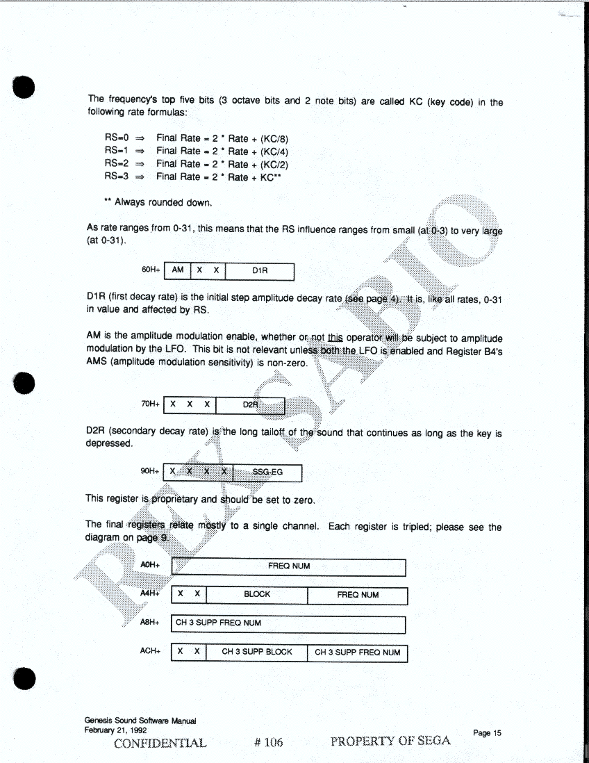
The frequency's top five bits (3 octave bits and 2 note bits) are called KC (Key code) in the following rate formulae:
| RS | Final rate |
| 0 | 2×Rate+(KC/8) |
| 1 | 2×Rate+(KC/4) |
| 2 | 2×Rate+(KC/2) |
| 3 | 2×Rate+(KC/1) |
(KC/n) is always rounded down
As Rate ranges from 0-31, this means that the RS influence ranges from small (at 0-3) to very large (at 0-31).
Register 60H+ - first decay rate; amplitude modulation
| D7 | D6 | D5 | D4 | D3 | D2 | D1 | D0 | |
| 60H+ | AM | D1R | ||||||
D1R (first decay rate) is the initial steep amplitude decay rate (see page 4). It is, like all rates, 0-31 in value and affected by RS.
AM is the amplitude modulation enable, whether of not this operator will be subject to amplitude modulation by the LFO. This bit is not relevant unless both the LFO is enabled and register B4's AMS (amplitude modulation sensitivity) is non-zero.
Register 70H+ - secondary decay rate
| D7 | D6 | D5 | D4 | D3 | D2 | D1 | D0 | |
| 70H+ | D2R | |||||||
D2R (secondary decay rate) is the long tail off of the sound that continues as long as the key is depressed.
This section not found in the linked scans
Register 80H+ - secondary amplitude; release rate
| D7 | D6 | D5 | D4 | D3 | D2 | D1 | D0 | |
| 80H+ | D1L | RR | ||||||
D1L is the secondary amplitude reached after the first period of rapid decay. It should be multiplied by 8 if one wishes to compare it to TL. Again as TL, the higher the number, the more attenuated the sound.
RR is the release rate, the final sharp decrease in volume after the key is released. All rates are 5 bit numbers, but there are only four bits available in the register. Thus, for comparison and calculation purposes, these four bits are the MSBs and the LSB is always 1. In other words, double it and add one.
Back to the scans...
Register 90H+ - proprietary
| D7 | D6 | D5 | D4 | D3 | D2 | D1 | D0 | |
| 90H+ | SSG-EG | |||||||
This register is proprietary and should be set to zero.
The final registers relate mostly to a single channel. Each register is tripled; please see the diagram on page 9.
Registers A0H-AFH - frequency
| D7 | D6 | D5 | D4 | D3 | D2 | D1 | D0 | |
| A0H+ | Frequency number LSB | |||||||
| A4H+ | Block | Frequency number MSB | ||||||
| A8H+ | Ch3 supplementary frequency number | |||||||
| ACH+ | Ch3 supplementary block | Ch3 supplementary frequency number | ||||||
Channel 1's frequency is in A0 and A4H.
Channel 2's frequency is in A1 and A5H.
Channel 3's frequency, if it is in normal mode (please see page 12), is in A2 and A6H.
If Channel 3 is in special mode:
Operator 1's frequency is in A2 and A6H
Operator 2's frequency is in A8 and ACH
Operator 3's frequency is in A9 and ADH
Operator 4's frequency is in AA and AEH
The frequency is a 14-bit number that should be set high byte, low byte (e.g. A4H then A0H). The highest 3 bits, called the "block", give the octave. The next 10 bits give the position in the octave, and a possible 12-tone sequence is:
Low                                                              High
617   653   692   733   777   823   872   924   979  1037  1099  1164
   635   372   392   755   800   847   898   951   1008  1131  1199
   (36)  (39)  (41)  (44)  (46)  (49)  (52)  (55)  (58)  (62)  (70)
(all numbers in base 10)
This sequence should be used inside each octave.
Register B0H+ - feedback; algorithm
| D7 | D6 | D5 | D4 | D3 | D2 | D1 | D0 | |
| B0H+ | Feedback | Algorithm | ||||||
Feedback is the degree to which operator 1 feeds back into itself. In the voice library, self feedback is represented as this:

The algorithm is the type of inter-operator connection used. Please see the list of the eight operators on page 3.
Register B4H+ - stereo; LFO sensitivity
| D7 | D6 | D5 | D4 | D3 | D2 | D1 | D0 | |
| B4H+ | L | R | AMS | FMS | ||||
Register B4H contains stereo output control and LFO sensitivity control.
| L | Left Output, 1 is on, 0 is off. |
| R | Right Output, 1 is on, 0 is off. |
NOTE: The stereo may only be heard by headphones.
Or with an AV lead connected to the headphone socket... or in an emulator.
AMS (amplitude modulation sensitivity) and FMS (frequency modulation sensitivity) are the degree to which the channel is affected by the LFO. If the LFO is disabled. this register need not be set. Additionally, amplitude modulation is also enabled on an operator-by-operator level.
| AMS | 0 | 1 | 2 | 3 |
| Sensitivity /dB | 0 | 1.4 | 5.9 | 11.8 |
| FMS | 0 | 1 | 2 | 3 | 4 | 5 | 6 | 7 |
| % of a halftone | 0 | ±3.4 | ±6.7 | ±10 | ±14 | ±20 | ±40 | ±80 |
Test program
Here's a tested power-on initialization and sample note in the "Grand Piano" voice (page 27)
Page 27 presumably has some sample instrument parameters... but is not included in sega2.doc or the scans.
| Register | Value | Comments |
| 22H | 0 | LFO off |
| 27H | 0 | Channel 3 mode normal |
| 28H | 0 | All channels off |
| 1 | ||
| 2 | ||
| 4 | ||
| 5 | ||
| 6 | ||
| 2BH | 0 | DAC off |
| 30H | 71H | DT1/MUL |
| 34H | 0DH | |
| 38H | 33H | |
| 3CH | 01H | |
| 40H | 23H | Total Level |
| 44H | 2DH | |
| 48H | 26H | |
| 4CH | 00H | |
| 50H | 5FH | RS/AR |
| 54H | 99H | |
| 58H | 5FH | |
| 5CH | 94H | |
| 60H | 5 | AM/D1R |
| 64H | 5 | |
| 68H | 5 | |
| 6CH | 7 | |
| 70H | 2 | D2R |
| 74H | 2 | |
| 78H | 2 | |
| 7CH | 2 | |
| 80H | 11H | D1L/RR |
| 84H | 11H | |
| 88H | 11H | |
| 8CH | A6H | |
| 90H | 0 | Proprietary |
| 94H | 0 | |
| 98H | 0 | |
| 9CH | 0 | |
| B0H | 32H | Feedback/algorithm |
| B4H | C0H | Both speakers on |
| 28H | 00H | Key off |
| A4H | 22H | Set frequency |
| A0H | 69H | |
| 28H | F0H | Key on |
| <Wait> | ||
| 28H | 00H | Key off |
Notes:
- Write address then data.
- Loop until read register D7 becomes 0
- Follow MSB/LSB sequence.
