YM2413 FM Operator Type-LL (OPLL) Application Manual
This document is an HTML conversion of these scans of an original document by Ricardo Bittencourt. This document typed by Maxim in 2003. Shading indicates additions/corrections/comments.
Table of Contents
- What is OPLL?
- Functions
- Description of Operation
- Interfacing
- Synthesis of Music Sounds
- Electrical Characteristics
- Timing Diagrams
- Outline Dimensions
Original page numbers
1 - 2 - 3 - 4 - 5 - 6 - 7 - 8 - 9 - 10 - 11 - 12 - 13 - 14 - 15 - 16 - 17 - 18 - 19 - 20 - 21 - 22 - 23 - 24 - 25 - 26 - 27
I. What is OPLL?
(I-1) Outline
This LL-Type FM Operator incorporates a DA Converter and a Quartz Oscillator in addition to a YAMAHA original FM Sound Generator, allowing for a much easier and more economical sound generating system assembly than conventional LSIs. Tone data are stored in ROM for software simplicity, making it possible to execute data alterations involved in tone changes with just one Instruments selection operation. Furthermore, a built-in Tone Data Register with capacity to store one tone allows for the generation of sound effects and original tones. Tones applicable to the "CAPTAIN" and TELETEXT are included among built-in tone data.
(I-2) Features
- FM Sound Generator for real sound creation.
- Two selectable modes: 9 simultaneous sounds or 6 melody sounds plus 5 rhythm sounds (different tones can be used together in either case).
- Built-in Instruments data (15 melody tones, 5 rhythm tones, "CAPTAIN" and TELETEXT applicable tones).
- Built-in DA Converter.
- Built-in Quartz Oscillator.
- Built-in Vibrato Oscillator/AM Oscillator.
- TTL Compatible Input.
- Si-Gate NMOS LSI.
- A single 5V power source.
(I-3) Sound Synthesis by FM
This is a method that makes use of harmonics generated by modulation to synthesize musical sounds. Circuitry to realize this method is relatively simple and is capable of generating waveforms including high order harmonics and un-harmonious sounds. It is known that relationships between the modulation index and the spectrum of harmonics are so natural that it is possible to synthesize a wide variety of sounds from natural musical instruments to artificial sounds.
This method is expressed with four parameters as follows.
(1) F = A sin (ωct + I sin (ωmt))
Where A is the amplitude of output, I modulation index, ωc and ωm angular frequencies of carrier and modulator respectively. The equation (1) can be expressed alternately as follows.
(2) F = A (J0(I) sin (ωct) + J1(I) (sin ((ωc + ωm) t) - sin ((ωc - ωm) t) + J2(I) (sin ((ωc + 2ωm) t) - sin ((ωc - 2ωm) t) + ...
Where Jn(I) is the nth-order Bessel function of the first kind. The amplitude of each harmonic component is expressed as a Bessel function of the modulation index. Sound synthesis by FM is found to be useful to obtain specific musical sounds or sound effects. String sounds, however, cannot be obtained as the distribution of harmonics is not uniform. A method called
"Feedback FM" has been incorporated to solve the problem. This method is characterized by the following equation:
(3) F = A sin (ωct + βF)
Where β is the rate of feedback. The spectrum of harmonics produced by "feedback FM" has a saw-tooth waveform and therefore it can be used to synthesize string sounds.
Three function blocks, as follows, are needed to realize the above method of sound synthesis by FM.
- Phase generator (PG) generating ωc
- Envelope generator (EG) generating amplitude A and modulation index (I) which vary with time
- Sin table (SIN)
The method of sound synthesis by FM can be realized by Figure I-1 with units (operator cells) which combine the three function blocks. By this method, all we have to do is to define a frequency parameter and EG parameters.
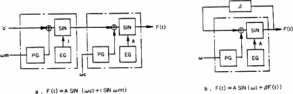
Figure I-1 Sound synthesis by FM with units
II. Functions
(II-1) Primary Functions
This OPLL is an FM Sound Generator LSI with a built-in 9-Bit DA Converter. It has two sound generation modes: 9 melody sounds or 6 melody sounds plus 5 rhythm sounds, both allowing for simultaneous generation of different tones, Selection between these two modes can be performed from the software. One of the special features of the LSI is its built-in Instruments ROM. As shown in the table hereunder, this ROM incorporates 15 melody tones and 5 rhythm tones, as well as all tones used for "CAPTAIN" and TELETEXT. Furthermore, a built-in Tone Register with capacity to store one tone allows for the creation of sound effects and original sounds. By controlling the parameters of this register (E, ω1, I and ω2 in the equation below), all kinds of harmonics can be created on the basis of the sample wave ω1.
FM = E sin (ω1t + I sin (ω2t))
Unlike conventional FM sound generators, this OPLL has a built-in Instruments ROM, permitting a substantial simplification of sound generation commands from the processor. First, the desired Instruments code is stored in the Instruments Selection Register. Then, after data has been input at the fixed intervals and timing, the unit starts generating sound. Automatic Processor play can be easily performed by writing data appropriate to the desired music into the Sustain and Volume registers. For using an original tone, the Instruments Selection Register must be cleared after writing data into the Tone Register as explained above. Rhythm sounds are generated by turning ON or OFF the corresponding bits in the Rhythm Control Register. In this case, the specified data must be input into the Key ON/OFF and F-Number Registers 8CH and 9CH.
(II-2) Pin Assignment
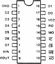
(II-3) Pin Functions
| Symbol | I/O | Function | ||||||||||||||||||||||||
| XIN | I | A quartz oscillator (3.579545 MHz) is connected between these two points. | ||||||||||||||||||||||||
| XOUT | O | |||||||||||||||||||||||||
| D0~D7 | I/O | 8-Bit Data Bus for OPLL control. | ||||||||||||||||||||||||
| A0 | I | For controlling the D0~D7 Data Bus.
| ||||||||||||||||||||||||
| I | Resets the system when the level is low, clearing OPLL Registers. | |||||||||||||||||||||||||
| MO | O | Melody (MO) and Rhythm (RO) outputs. Both outputs are source followers. Integrated circuitry and an amplifier are necessary for subsequent processing. | ||||||||||||||||||||||||
| RO | ||||||||||||||||||||||||||
| VCC | I | +5V Power Pin. | ||||||||||||||||||||||||
| GND | - | Ground Pin. |
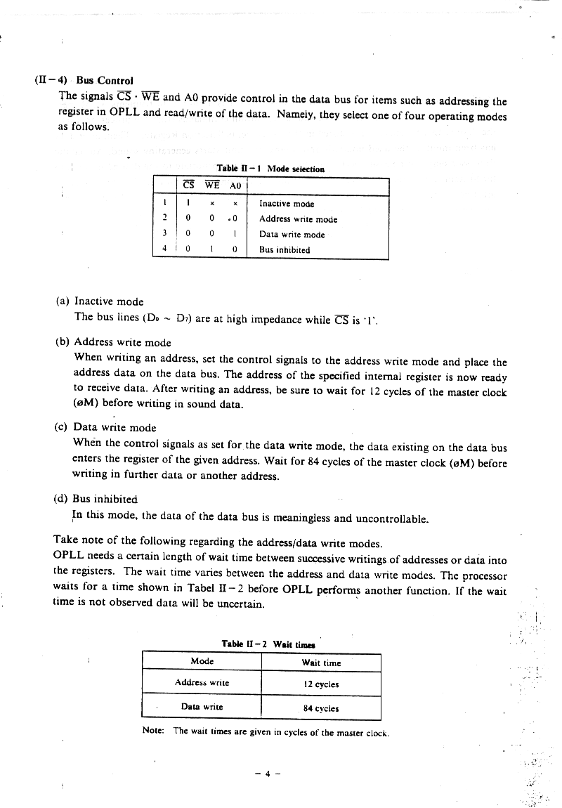
(II-4) Bus Control
The signals , and A0 provide control in the data bus for items such as addressing the register in OPLL and read/write of the data. Namely, they select one of the four operating modes as follows.
| A0 | ||||
| 1 | 1 | * | * | Inactive mode |
| 2 | 0 | 0 | 0 | Address write mode |
| 3 | 0 | 0 | 1 | Data write mode |
| 4 | 0 | 1 | 0 | Bus inhibited |
- Inactive mode
The bus lines (D0~D7) are at high impedance while is '1'. - Address Write mode
When writing an address, set the control signals to the address write mode and place the address data on the data bus. The address of the specified internal register is now ready to receive data. After writing an address, be sure to wait 12 cycles of the master clock (øM) before writing in sound data. - Data write mode
When the control signals as (are) set for the data write mode, the data existing on the data bus enters the register of the given address. Wait for 84 cycles of the master clock (øM) before writing in further data or another address. - Bus inhibited
In this mode, the data of (on) the data bus is meaningless and uncontrollable.
Take note of the following regarding the address/data modes.
OPLL needs a certain length of wait time between successive writings of addresses or data into the registers. The wait time varies between address and data write modes. The processor waits for a time in Table II-2 before OPLL performs another function. If the wait time is not observed data will be uncertain.
| Mode | Wait time |
| Address write | 12 cycles |
| Data write | 84 cycles |
Note: the wait times are given in cycles of the master clock.
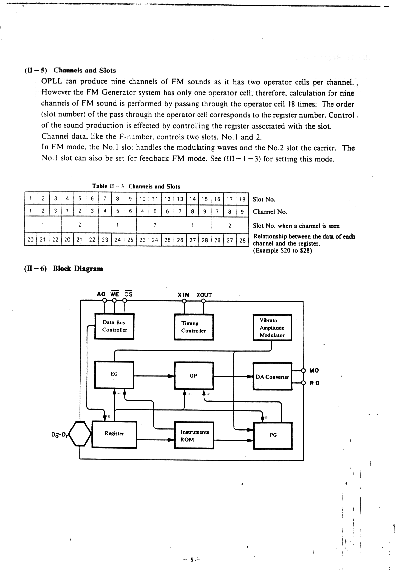
(II-5) Channels and Slots
OPLL can produce nine channels of FM sounds as it has two operator cells per channel. However, the FM Generator system has only one operator cell, therefore, calculation for nine channels of FM sound is performed by passing through the operator cell 18 times. The order (slot number) of the pass through the operator cell corresponds to the register number. Control of the sound production is effected by controlling the register associated with the slot.
Channel data, like the F-number, controls two slots, No. 1 and 2.
In FM mode, the No. 1 slot handles the modulating waves and the No. 2 slot the carrier. The No. 1 slot can also be set for feedback FM mode. See (III-1-3) for setting this mode.
| 1 | 2 | 3 | 4 | 5 | 6 | 7 | 8 | 9 | 10 | 11 | 12 | 13 | 14 | 15 | 16 | 17 | 18 | Slot No. |
| 1 | 2 | 3 | 1 | 2 | 3 | 4 | 5 | 6 | 4 | 5 | 6 | 7 | 8 | 9 | 7 | 8 | 9 | Channel No. |
| 1 | 2 | 1 | 2 | 1 | 2 | Slot No. when a channel is seen | ||||||||||||
| 20 | 21 | 22 | 20 | 21 | 22 | 23 | 24 | 25 | 23 | 24 | 25 | 26 | 27 | 28 | 26 | 27 | 28 | Relationship between the data of each channel and the register. (Example $20 to $28) |
(II-6) Block Diagram
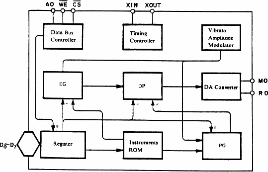
(II-7) Register Map
| Address | D7 | D6 | D5 | D4 | D3 | D2 | D1 | D0 | |
| 00 | AM | VIB | EG-TYP | KSR | MUL | User Tone Register (c):Carrier (m): Modulator | |||
| 01 | |||||||||
| 02 | KSL | TL | |||||||
| 03 | DC | DM | FB | ||||||
| 04 | AR | DR | |||||||
| 05 | |||||||||
| 06 | SL | RR | |||||||
| 07 | |||||||||
| 0E | R | BD | SD | TOM | T-CY | HH | Rhythm Control | ||
| 0F | TEST | OPLL Test Data (Normal '0') | |||||||
| 10~18 | F-Num. 0~7 | F-Number LSB 8 bits | |||||||
| 20~28 | SUS ON/OFF | KEY ON/OFF | BLOCK 0~2 | F-Num. 8 | F-Number MSB, octave set Key ON/OFF register Sustain ON/OFF register | ||||
| 30~38 | INST | VOL | Instruments Selection and Volume Register | ||||||
Register map for Rhythm mode (addr. $0E D5 = 'H')
| Address | D7 | D6 | D5 | D4 | D3 | D2 | D1 | D0 | |
| 36 | BD-VOL | Rhythm volume register | |||||||
| 37 | HH-VOL | SD-VOL | |||||||
| 38 | TOM-VOL | T-CY-VOL | |||||||
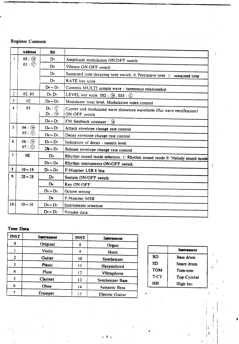
Register Contents
| Address | Bit | ||
| 1 | 00 (m) 01 (c) | D7 | Amplitude modulation ON/OFF switch |
| D6 | Vibrato ON/OFF switch | ||
| D5 | Sustained tone/decaying tone switch. 0: Percussive tone 1: sustained tone | ||
| D4 | RATE key scale | ||
| D0~D3 | Controls Multiple sample wave-harmonics relationship | ||
| 2 | 02 (m) 03 (c) | D6 D7 | LEVEL key scale |
| 3 | 02 | D0~D5 | Modulator total level. Modulation index control |
| 4 | 03 | D4 (c) D3 (m) | Carrier and modulated wave distortion waveform (flat wave rectification) ON/OFF switch |
| D0~D2 | FM feedback constant (m) | ||
| 5 | 04 (m) 05 (c) | D4~D7 | Attack envelope change rate control |
| D0~D3 | Decay envelope change rate control | ||
| 6 | 06 (m) 07 (c) | D4~D7 | Indication of decay-sustain level |
| D0~D3 | Release envelope change rate control | ||
| 7 | 0E | D5 | Rhythm sound mode selection. 1: Rhythm sound mode 0: Melody sound mode |
| D0~D4 | Rhythm instruments ON/OFF switch | ||
| 8 | 10~18 | D0~D7 | F-Number LSB 8 bits |
| 9 | 20~28 | D5 | Sustain ON/OFF switch |
| D4 | Key ON/OFF switch | ||
| D1~D3 | Octave setting | ||
| D0 | F-Number MSB | ||
| 10 | 30~38 | D4~D7 | Instruments selection |
| D0~D3 | Volume data |
Tone Data
| INST | Instrument |
| 0 | Original |
| 1 | Violin |
| 2 | Guitar |
| 3 | Piano |
| 4 | Flute |
| 5 | Clarinet |
| 6 | Oboe |
| 7 | Trumpet |
| 8 | Organ |
| 9 | Horn |
| 10 | Synthesizer |
| 11 | Harpsichord |
| 12 | Vibraphone |
| 13 | Synthesizer Bass |
| 14 | Acoustic Bass |
| 15 | Electric Guitar |
| BD | Bass Drum |
| SD | Snare Drum |
| TOM | Tom-tom |
| T-CY | Top Cymbal |
| HH | High Hat |
III. Description of Operation
All functions of the OPLL are controlled by data written in a register array by the processor. The data specifies the sound envelope shape, the degree of modulation, frequency, and output mode, etc. A complete set of data defines the sound as that of a piano or violin, etc. For the use of complex varieties of data sets se "Synthesis of music sounds".
(III-1) Registers
A register comprises an area of 271 bits, as shown in the address map II-7. The address referred to here is the sub-address assigned to each operator of the OPLL. Musical sound data will be written into a register referred to by the sub-address. To store a data in the OPLL, we send a sub-address and then the sound data. If we access a location having the same sub-address many times, we only have to send the sub-address the first time. In subsequent accesses, we can send sound data alone to renew old data.
All registers are cleared to 0 by initialization (initial clear terminal = 0).
(III-1-1) TEST: Address [$0F]
This address is established to test the LSI.
Normally all addresses are 0.
(III-1-2) AM/VIB/EG-TYP/KSR/MUL: Address [$00~$01]
This register controls the multiplying factor that converts F-number into the carrier ($01) and modulator ($00) frequencies which matches the sound frequency components, and the envelope shape etc.
| D7 | D6 | D5 | D4 | D3 | D2 | D1 | D0 |
| AM | VIB | EG-TYP | KSR | MUL | |||
| 23 | 22 | 21 | 20 | ||||
- D0~D3 (MUL): The frequencies of the carrier wave and the modulated wave are controlled according to the multiplying factors in Table III-1.
<Example>
F(t) = E sin (ωft + I sin (7 ωft))
- Frequency according to F-number = ωft
- Carrier MUL = 1
- Modulator MUL = 7
Table III-1 Multiplying factors
| MUL | Multiplying factor |
| 0 | ½ |
| 1 | 1 |
| 2 | 2 |
| 3 | 3 |
| 4 | 4 |
| 5 | 5 |
| 6 | 6 |
| 7 | 7 |
| 8 | 8 |
| 9 | 9 |
| A | 10 |
| B | 10 |
| C | 12 |
| D | 12 |
| E | 15 |
| F | 15 |
- D4 (KSR): This bit specifies the key scale of RATE.
Since almost all musical steps become high for natural instruments, the sound can quickly change to high or low. This is accomplished by the key scale of RATE. Values in Table III-2 include the speed offset for the musical steps. Therefore, the actual RATE set for the ADSR will be these values which include the offset.
RATE = 4 × R + Rks
- R is the set value for ADSR
- Rks is the key scale offset value
- Note that when R=0, RATE=0
| 0 | 1 | 2 | 3 | 4 | 5 | 6 | 7 | Octave | ||||||||
| 0 | 1 | 2 | 3 | 4 | 5 | 6 | 7 | BLOCK Data | ||||||||
| 0 | 1 | 0 | 1 | 0 | 1 | 0 | 1 | 0 | 1 | 0 | 1 | 0 | 1 | 0 | 1 | F-Num MSB |
| 0 | 0 | 0 | 0 | 1 | 1 | 1 | 1 | 2 | 2 | 2 | 2 | 3 | 3 | 3 | 3 | D4 = 0 key scale |
| 0 | 1 | 2 | 3 | 4 | 5 | 6 | 7 | 8 | 9 | 10 | 11 | 12 | 13 | 14 | 15 | D4 = 1 key scale |
- D5 (EG-TYP): Switching between sustained tone and Percussive tone.
When D5 = '0' it will be percussive tone. When D5 = '1' it will be sustained tone. These sound modes are different in that the RELEASE RATE usage differs. The difference is shown in Figure III-1.
Percussive tone (D5 = 0)
Sustained tone (D5 = 1)
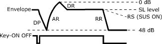
Fig. III-1
- D4 (VIB): Vibrato on/off switch. When this bit is '1', vibrato will be applied to the slot. The frequency is 6.4 Hz (@ øM = 3.6 MHz).
- D7 (AM): Amplitude modulation on/off switch. When this bit is '1', amplitude modulation wil be epplied to the slot. The frequency is 3.7 Hz (@ øM = 3.6 MHz).
(III-1-3) KSL/TL/DC/DM/FB: Address [$02~$03]
Total Level is used to control the modulation index (tone) by adding attenuation to the output of the envelope generator. Level key scale (KSL) ensures, like the key scale of RATE, that the output level of natural instruments falls as the pitch of sound rises.
| D7 | D6 | D5 | D4 | D3 | D2 | D1 | D0 | |
| $02 | KSL | TL | ||||||
| $03 | DC | DM | FB | |||||
- D0~D5 (TL): The minimum resolution of the attenuation level is 0.75 dB and the sound level can be reduced down to 47.25 dB.
| D5 | D4 | D3 | D2 | D1 | D0 | |
| Attenuation level | 24 dB | 12 dB | 6 dB | 3 dB | 1.5 dB | 0.75 dB |
- D6~D7 (KSL): This bit controls the level of key scaling. In key scale mode, the level of attenuation increases as pitch rises, to 1.5 dB/oct, 3 dB/oct, 6 dB/oct, and 0 dB/oct.
| D7 | D6 | Attenuation rate |
| 0 | 0 | 0 dB/oct |
| 1 | 0 | 1.5 dB/oct |
| 0 | 1 | 3 dB/oct |
| 1 | 1 | 6 dB/oct |
Table III-5 Attenuation at each F-Number at 3 dB/OCT
| OCT | F-Number | |||||||||||||||
| 0 | 1 | 2 | 3 | 4 | 5 | 6 | 7 | 8 | 9 | 10 | 11 | 12 | 13 | 14 | 15 | |
| 0 | 0 | 0 | 0 | 0 | 0 | 0 | 0 | 0 | 0 | 0 | 0 | 0 | 0 | 0 | 0 | 0 |
| 1 | 0 | 0 | 0 | 0 | 0 | 0 | 0 | 0 | 0 | 0.75 | 1.125 | 1.5 | 1.875 | 2.25 | 2.525 | 3 |
| 2 | 0 | 0 | 0 | 0 | 0 | 1.125 | 1.875 | 2.525 | 3 | 3.75 | 4.125 | 4.5 | 4.875 | 5.25 | 5.625 | 6 |
| 3 | 0 | 0 | 0 | 1.875 | 3 | 4.125 | 4.875 | 5.625 | 6 | 6.75 | 7.125 | 7.5 | 7.875 | 8.25 | 8.625 | 9 |
| 4 | 0 | 0 | 3 | 4.875 | 6 | 7.125 | 7.875 | 8.625 | 9 | 9.75 | 10.125 | 10.5 | 10.875 | 11.25 | 11.625 | 12 |
| 5 | 0 | 3 | 6 | 7.875 | 9 | 10.125 | 10.875 | 11.625 | 12 | 12.75 | 13.125 | 13.5 | 13.875 | 14.25 | 14.825 | 15 |
| 6 | 0 | 6 | 9 | 10.875 | 12 | 13.125 | 13.875 | 14.825 | 15 | 15.75 | 16.125 | 16.5 | 16.875 | 17.25 | 17.625 | 18 |
| 7 | 0 | 9 | 12 | 13.875 | 15 | 16.125 | 16.875 | 17.625 | 18 | 18.75 | 19.125 | 19.5 | 19.875 | 20.25 | 20.625 | 21 |
Unit: dB
Notes:
- F-Number is the value of the four MSBs.
- Half of the above data at 1.5 dB/oct
- Double of the above at 6 dB/oct
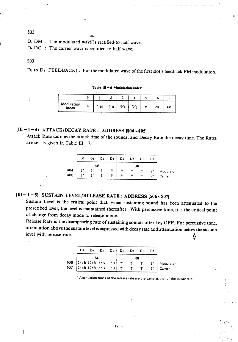
- $03: D3 (DM): The modulated wave is rectified to half wave.
- $03: D4 (DC): The carrier wave is rectified to half wave.
- $03: D0~D2 (FB): For the modulated wave of the first slot's feedback FM modulation.
| 0 | 1 | 2 | 3 | 4 | 5 | 6 | 7 | |
| Modulation index | 0 | π/16 | π/8 | π/4 | π/2 | π | 2π | 4π |
(III-1-4) AR/DR: Address [$04~$05]
Attack Rate defines the attack time of the sounds, and Decay Rate the decay time. The Rates are set as given in Table III-7.
| D7 | D6 | D5 | D4 | D3 | D2 | D1 | D0 | ||
| AR | DR | ||||||||
| $04 | 23 | 22 | 21 | 20 | 23 | 22 | 21 | 20 | Modulator |
| $05 | 23 | 22 | 21 | 20 | 23 | 22 | 21 | 20 | Carrier |
(III-1-5) SL/RR: Address [$06~$07]
Sustain Level is the critical point that, when sustaining sound has been attenuated to the prescribed level, the level is maintained thereafter. With percussive tone, it is the critical point of change from decay mode to release mode.
Release Rate is the disappearing rate of sustaining sounds after key OFF. For percussive tone, attenuation above the sustain level is expressed with decay rate and attenuation below the sustain level with release rate.
| D7 | D6 | D5 | D4 | D3 | D2 | D1 | D0 | ||
| SL | RR | ||||||||
| $06 | 24 dB | 12 dB | 6 dB | 3 dB | 23 | 22 | 21 | 20 | Modulator |
| $07 | 24 dB | 12 dB | 6 dB | 3 dB | 23 | 22 | 21 | 20 | Carrier |
- Attenuation times of the release rate are the same as that of the decay rate.
Table III-7 Attack and decay times in relation to RATE
RATE given below is that of the after key scale. RATE = RM × 4 + RL
| RATE | EG decay time | EG attack time | |||
| RM | RL | 0 dB - 40 dB | 10% - 90% | 0 dB - 40 dB | 10% - 90% |
| 15 | 3 | 1.27 | 0.52 | 0.00 | 0.00 |
| 15 | 2 | 1.27 | 0.52 | 0.00 | 0.00 |
| 15 | 1 | 1.27 | 0.52 | 0.00 | 0.00 |
| 15 | 0 | 1.27 | 0.52 | 0.00 | 0.00 |
| 14 | 3 | 1.47 | 0.60 | 0.14 | 0.10 |
| 14 | 2 | 1.71 | 0.60 | 0.18 | 0.12 |
| 14 | 1 | 2.05 | 0.82 | 0.22 | 0.14 |
| 14 | 0 | 2.55 | 1.03 | 0.28 | 0.18 |
| 13 | 3 | 2.94 | 1.21 | 0.30 | 0.22 |
| 13 | 2 | 3.42 | 1.37 | 0.34 | 0.22 |
| 13 | 1 | 4.10 | 1.65 | 0.42 | 0.26 |
| 13 | 0 | 5.11 | 2.05 | 0.50 | 0.32 |
| 12 | 3 | 5.87 | 2.41 | 0.54 | 0.36 |
| 12 | 2 | 6.84 | 2.74 | 0.60 | 0.38 |
| 12 | 1 | 8.21 | 3.30 | 0.70 | 0.44 |
| 12 | 0 | 10.22 | 4.10 | 0.84 | 0.54 |
| 11 | 3 | 11.75 | 4.03 | 0.97 | 0.64 |
| 11 | 2 | 13.60 | 5.47 | 1.13 | 0.72 |
| 11 | 1 | 16.41 | 6.60 | 1.37 | 0.84 |
| 11 | 0 | 20.44 | 8.21 | 1.69 | 1.09 |
| 10 | 3 | 23.49 | 9.65 | 1.93 | 1.29 |
| 10 | 2 | 27.36 | 10.94 | 2.25 | 1.45 |
| 10 | 1 | 32.03 | 13.19 | 2.74 | 1.69 |
| 10 | 0 | 40.07 | 16.41 | 3.30 | 2.17 |
| 9 | 3 | 46.99 | 19.31 | 3.86 | 2.57 |
| 9 | 2 | 54.71 | 12.80 | 4.51 | 2.98 |
| 9 | 1 | 65.65 | 26.39 | 5.47 | 3.30 |
| 9 | 0 | 81.74 | 32.03 | 6.76 | 4.34 |
| 8 | 3 | 93.97 | 38.62 | 7.72 | 5.15 |
| 8 | 2 | 109.42 | 43.77 | 9.01 | 5.79 |
| 8 | 1 | 131.31 | 52.78 | 10.94 | 6.76 |
| 8 | 0 | 163.49 | 65.65 | 13.52 | 8.69 |
| 7 | 3 | 187.95 | 77.24 | 15.45 | 10.30 |
| 7 | 2 | 218.84 | 87.54 | 18.02 | 11.59 |
| 7 | 1 | 262.61 | 185.56 | 21.00 | 13.52 |
| 7 | 0 | 326.98 | 131.31 | 27.03 | 17.30 |
| 6 | 3 | 375.98 | 154.40 | 30.90 | 20.60 |
| 6 | 2 | 437.69 | 175.07 | 36.04 | 23.17 |
| 6 | 1 | 525.22 | 211.12 | 43.77 | 27.03 |
| 6 | 0 | 653.95 | 262.61 | 54.87 | 34.76 |
| 5 | 3 | 751.79 | 308.96 | 61.79 | 41.19 |
| 5 | 2 | 875.37 | 350.15 | 72.89 | 46.34 |
| 5 | 1 | 1050.45 | 422.24 | 87.54 | 54.07 |
| 5 | 0 | 1307.91 | 525.22 | 108.13 | 69.51 |
| 4 | 3 | 1503.58 | 617.91 | 123.50 | 82.39 |
| 4 | 2 | 1750.75 | 700.30 | 144.48 | 92.69 |
| 4 | 1 | 2180.89 | 844.40 | 175.07 | 108.13 |
| 4 | 0 | 2615.82 | 1050.45 | 216.27 | 139.63 |
| 3 | 3 | 3007.16 | 1235.82 | 247.16 | 164.70 |
| 3 | 2 | 3501.49 | 1400.60 | 280.36 | 185.37 |
| 3 | 1 | 4201.79 | 1680.95 | 358.15 | 216.27 |
| 3 | 0 | 5231.64 | 1280.89 | 432.54 | 278.06 |
| 2 | 3 | 6014.32 | 2471.64 | 494.33 | 329.55 |
| 2 | 2 | 7002.98 | 2801.19 | 576.72 | 370.75 |
| 2 | 1 | 8403.58 | 3377.91 | 780.30 | 432.54 |
| 2 | 0 | 10463.30 | 4201.79 | 865.88 | 556.12 |
| 1 | 3 | 12078.66 | 4943.20 | 988.66 | 659.11 |
| 1 | 2 | 14606.80 | 5602.39 | 1153.43 | 741.49 |
| 1 | 1 | 16807.20 | 6755.82 | 1400.60 | 865.80 |
| 1 | 0 | 20926.60 | 8403.58 | 1730.15 | 1112.24 |
Likely transcription errors here, especially lower in the table
Note: When RATE is '0', the envelope will not change.
(III-1-6) BLOCK/F-Number/SUS/KEY: Address [$A0~$B8] Should say [$10-$28]
Data defining a musical scale and interval. The F-Number is contained in the registers $1* and $2*.
| D7 | D6 | D5 | D4 | D3 | D2 | D1 | D0 | |
| $10~$18 | F-Number | |||||||
| 27 | 26 | 25 | 24 | 23 | 22 | 21 | 20 | |
| $20~$28 | SUS | KEY | BLOCK | F-Num | ||||
| 22 | 21 | 20 | 28 | |||||
- D0~D7 [$1*], D0 [$2*] (F-Number): The F-Number is defined with 8 bits of the $1* register and LSB of $2*, for a total of 9 bits. This F-Number defines a scale (how a value is assigned to the F-number is described later).
- D1~D3 (BLOCK): Defines octave information.
- D4 (KEY): This bit indicates the ON/OFF state of the key. When this bit is '1', the associated channel is on and sound is produced. '0' is equivalent to Key-OFF.
- D5 (SUS): When this bit is '1', the RR with the key off will be 5.
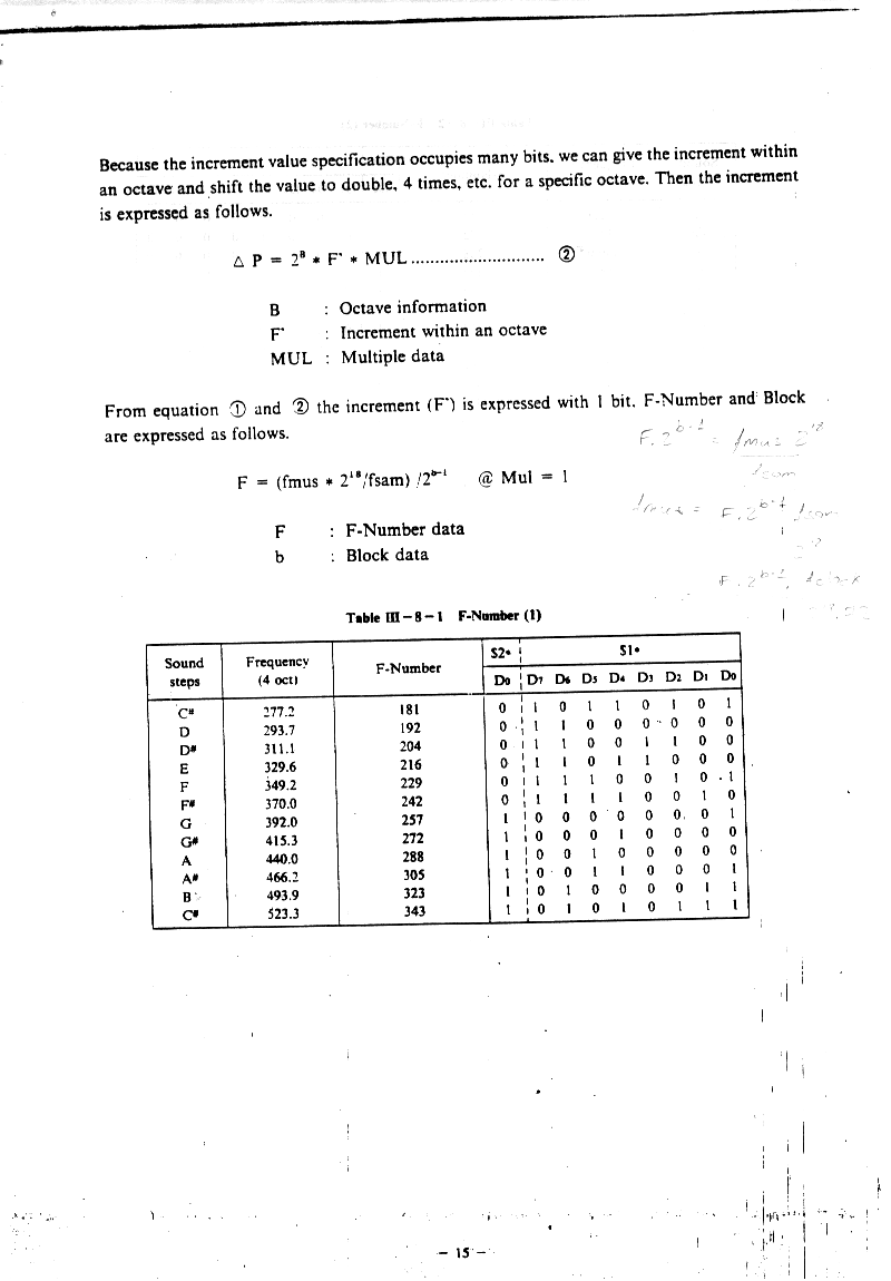
The OPLL generates the necessary frequency when an appropriate increment of phase is given. The increment is determined by the F-Number, Block, and Multiple information. The following formula gives the increment for a desired frequency.
(1) ΔP = fmus × 218 / fsam
- fsam = fM/72
- fmus: Desired frequency
- fsam: Sampling frequency (50 kHz)
- fM: Input clock frequency (3.6 MHz)
Because the increment value specification occupies many bits, we can give the increment within an octave and shift the value to double, 4 times, etc. for a specific octave. Then the instrument is expressed as follows.
(2) ΔP = 2B × F' × MUL
- B: Octave information
- F': Increment within an octave
- MUL: Multiple data
From equation (1) and (2) the increment (F') is expressed with 1 bit. F-Number and Block are expressed as follows.
F = (fmus × 218/fsam) / 2b-1 @ MUL = 1
- F: F-Number data
- b: Block data
| Sound steps | Frequency (4 oct) | F-Number | $2* | $1* | |||||||
| D0 | D7 | D6 | D5 | D4 | D3 | D2 | D1 | D0 | |||
| C# | 277.2 | 181 | 0 | 1 | 0 | 1 | 1 | 0 | 1 | 0 | 1 |
| D | 293.7 | 192 | 0 | 1 | 1 | 0 | 0 | 0 | 0 | 0 | 0 |
| D# | 311.1 | 204 | 0 | 1 | 1 | 0 | 0 | 1 | 1 | 0 | 0 |
| E | 329.6 | 216 | 0 | 1 | 1 | 0 | 1 | 1 | 0 | 0 | 0 |
| F | 349.2 | 229 | 0 | 1 | 1 | 1 | 0 | 0 | 1 | 0 | 1 |
| F# | 370.0 | 242 | 0 | 1 | 1 | 1 | 1 | 0 | 0 | 1 | 0 |
| G | 392.0 | 257 | 1 | 0 | 0 | 0 | 0 | 0 | 0 | 0 | 1 |
| G# | 415.3 | 272 | 1 | 0 | 0 | 0 | 1 | 0 | 0 | 0 | 0 |
| A | 440.0 | 288 | 1 | 0 | 0 | 1 | 0 | 0 | 0 | 0 | 0 |
| A# | 466.2 | 305 | 1 | 0 | 0 | 1 | 1 | 0 | 0 | 0 | 1 |
| B | 493.9 | 323 | 1 | 0 | 1 | 0 | 0 | 0 | 0 | 0 | 1 |
| C | 523.3 | 343 | 1 | 0 | 1 | 0 | 1 | 0 | 1 | 1 | 1 |
| Sound steps | Frequency (4 oct) | F-Number | $2* | $1* | |||||||
| D0 | D7 | D6 | D5 | D4 | D3 | D2 | D1 | D0 | |||
| G | 392.2 | 257 | 1 | 0 | 0 | 0 | 0 | 0 | 0 | 0 | 1 |
| G# | 415.3 | 272 | 1 | 0 | 0 | 0 | 1 | 0 | 0 | 0 | 0 |
| A | 440.0 | 288 | 1 | 0 | 0 | 1 | 0 | 0 | 0 | 0 | 0 |
| A# | 466.2 | 305 | 1 | 0 | 0 | 1 | 1 | 0 | 0 | 0 | 1 |
| B | 493.9 | 323 | 1 | 0 | 1 | 0 | 0 | 0 | 0 | 1 | 1 |
| C | 523.3 | 343 | 1 | 0 | 1 | 0 | 1 | 0 | 1 | 1 | 1 |
| C# | 554.4 | 363 | 1 | 0 | 1 | 1 | 0 | 1 | 0 | 1 | 1 |
| D | 587.3 | 385 | 1 | 1 | 0 | 0 | 0 | 0 | 0 | 0 | 1 |
| D# | 622.2 | 408 | 1 | 1 | 0 | 0 | 1 | 1 | 0 | 0 | 0 |
| E | 659.3 | 432 | 1 | 1 | 0 | 1 | 1 | 0 | 0 | 0 | 0 |
| F | 698.5 | 458 | 1 | 1 | 1 | 0 | 0 | 1 | 0 | 1 | 0 |
| F# | 740.0 | 485 | 1 | 1 | 1 | 1 | 0 | 0 | 1 | 0 | 1 |
(III-1-7) RHYTHM: Address [$0E]
To control ON/OFF of the Rhythm mode selection and percussion instruments.
| D5 | D4 | D3 | D2 | D1 | D0 |
| RHYTHM | BD | SD | TOM | TOP-CY | HH |
D0~D5 (RHYTHM): When D5 = 1, OPLL is in Rhythm mode with percussion sounds produced through channels 7~9 (see page 5). In this mode, the melody section is limited to six sounds. D0~D4 controls ON/OFF of percussion instruments. Therefore Key-ON bits $26, $27, $28 must always be cleared to 0. Slots 13~18 are related with percussion sounds as shown in Table III-9, and data of F-Num must input values that match percussion sounds.
| Instrument | Slot |
| BD | 13, 16 |
| SD | 17 |
| TOM | 15 |
| TOP-CYM | 18 |
| HH | 14 |
| Address | Data |
| 16 | 20 |
| 17 | 50 |
| 18 | C0 |
| 26 | 05 |
| 27 | 05 |
| 28 | 01 |
(III-1-8) INST/VOL: Address [$30~$38]
Determine the voice (15 voices preset in ROM and original voices) and the volume.
| D7 | D6 | D5 | D4 | D3 | D2 | D1 | D0 | |
| $30~$38 | INST | VOL | ||||||
- D4~D7 (INST): These four bits determine voices as follows:
| INST | Instrument |
| 0 | Original |
| 1 | Violin |
| 2 | Guitar |
| 3 | Piano |
| 4 | Flute |
| 5 | Clarinet |
| 6 | Oboe |
| 7 | Trumpet |
| 8 | Organ |
| 9 | Horn |
| A | Synthesizer |
| B | Harpsichord |
| C | Vibraphone |
| D | Synthesizer Bass |
| E | Acoustic Bass |
| F | Electric Guitar |
- D0~D3 (VOL): Determine the volume for the voices. The minimum resolution is 3 dB and the maximum 45 dB.
| D3 | D2 | D1 | D0 |
| 24 dB | 12 dB | 6 dB | 3 dB |
In the rhythm mode (addr = $0E, D5 = 'H'), each rhythm volume for $36~$38 are set as follows:
| Addr | D7 | D6 | D5 | D4 | D3 | D2 | D1 | D0 |
| $36 | BD | |||||||
| $37 | HH | SD | ||||||
| $38 | TOM | T-CYM | ||||||
(III-2) Phase Generator (PG)
The phase generator produces a phase value by accumulating increments that correspond to the frequency required at a given unit of time. The increment is generated from frequency data (F-Number, Block, and Multiple) sent from the registers. The frequency data is combined with the output of a built-in vibrato oscillator to produce a vibrato effect.
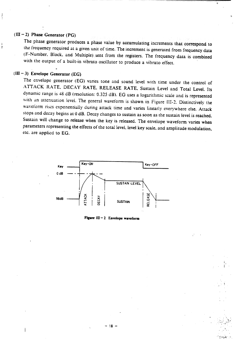
(III-3) Envelope Generator (EG)
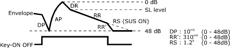
The envelope generator (EG) varies tone and sound level with time under the control of Attack Rate, Decay Rate, Release Rate, Sustain Level and Total Level. Its dynamic range is 48 dB (resolution: 0.325 dB). EG uses a logarithmic scale and is represented with an attenuation level. The general waveform is shown in Figure III-2. Distinctively the waveform rises exponentially during attack time and varies linearly everywhere else. Attack stops and decay begins at 0 dB. Decay changes to sustain as soon as the sustain level is reached. Sustain will change to release when the key is released. The envelope waveform varies when parameters representing the effects of the total level, level key scale, and amplitude modulation, etc, are applied to EG.
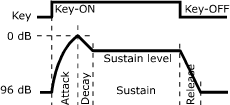
Figure III-2 Envelope waveform
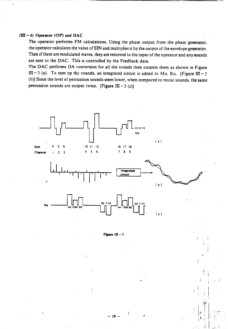
(III-4) Operator (OP) and DAC
The operator performs FM calculations. Using the phase output from the phase generator, the operator calculates the value of SIN and multiplies it by the output of the envelope generator. Then if there are modulated waves, they are returned to the input of the operator and any sounds are sent to the DAC. This is controlled by the Feedback data.
The DAC performs DA conversion for all the sounds then outputs them as shown in Figure III-3 (a). To sum up the sounds, an integrated circuit is added to MO/RO. (Figure III-3 (b)) Since the level of percussive sounds seems lower, when compared to musical sounds, the same percussive sounds are output twice. (Figure III-3 (c))
Figure III-3
IV. Interfacing
OPLL, controlled by a microprocessor or microcomputer, outputs an audio signal, being an analog signal converted with a D/A converter. To obtain sound from OPLL, it is necessary to interface it with other devices. This chapter describes interfacing.
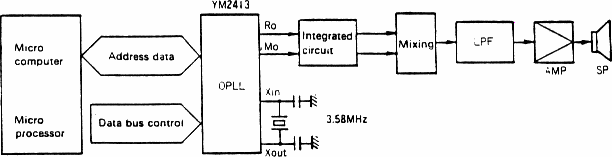
Figure IV-1 System block diagram
(IV-1) Clock Generation
OPLL operates in the range of 2 to 4 MHz. Amplitude modulation, the frequency of the vibrato oscillator, and attack decay speeds are designed to take 3.6 MHz (3.579545 MHz) as the reference frequency. Therefore, when this LSI is used, it will be economical to connect the quartz crystal oscillator (for color burst signals) with Xin Xout.
(IV-2) Audio Output Interface
An external integrated circuit is needed for the OPLL's music sound output, which is a pulse signal as described earlier. The output (and buffer) of this integrated circuit may be directly connected to an audio amplifier. For better sound quality, you can remove step noises by inserting a low-pass filter (cutoff frequency: 20kHz or so) between the integrated circuit and amplifier. Click noises accompanying power-ON/OFF will be necessary to protect the audion equipment (amplifier and speakers).
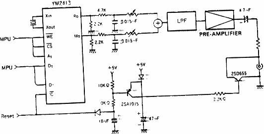
Figure IV-2 Audio interface
(IV-3) Interfacing microprocessor/microcomputer
D0~D7 of OPLL are the bidirectional bus lines which connect to a processor. OPLL exchanges address and data with the processor. The bus control signals , and A0 control transfer of data. It is possible to build up an FM sound source system with the minimum configuration of OPLL, memory and processor.
Figure IV-3 Interfacing processor
V. Synthesis of music sounds
This chapter describes what data to enter the OPLL registers in order to synthesize sound of the piano and brass.
(V-1) Procedure of Synthesizing Sounds
First, you have to analyze the sounds of the musical instrument which you want to synthesize by the FM method. For
example, the sound of a piano is characterized by a fast attack and, if the key is held down, a gradual delay. The will sound (sound will) include many overtones at the attack time however, as time elapses, overtones disappear, resulting in a different overtone composition. When you are aware (of) such characteristics, you are better able to synthesize the sounds by the FM method. The output amplitude can be determined from the characteristics of the envelope form and the modulation index from the overtone composition. Frequency ratio can also be determined roughly from the overtone composition because the frequency of the operator is related to it. In this way, you can determine the FM parameters roughly from characteristics of the sounds and, by listening to the synthesized sound, make minor corrections to obtain a more desirable result.
(V-2) Fundamentals of Sound Synthesis
The FM sound source makes use of carrier wave modulation by the modulator.
Since the FM's basic parameter (carrier output level, modulator output level, modulator feedback level, carrier frequency, modulator frequency) is handled effectively, the pitch, tone and volume of sounds can all be decided. Table V-1 shows the relationship between FM parameters and OPLL parameters.
(V-3) Examples of Sound Synthesis
Table V-1 Fundamentals of sound synthesis
| Item | Related parameters | MIN <- (Change of sounds) -> MAX |
| Output level of carrier | TOTAL LEVEL (Data of A, D, S, R and key scale data) | Low volume <-> High volume |
| Output level of modulator | Dull sound <-> Bright sound | |
| Feedback level of modulator | FB | Ordinary tone <-> Sharp tone (Noise) |
| Carrier frequency | MULTI (BLOCK/F-Number) | Low pitch <-> High pitch |
| Frequency of modulator | Near overtone <-> Far overtone |
- Electric piano
- Determination of operator frequencies
Set MUL to '1', for both operators, to produce an overtone of higher frequency. (Increases are integer multiples)
- Determination of operator frequencies
- Output level of the operator
Change the output of the modulator to adjust the tone. When determining the level of operator 1, adjust the sounds for rich overtones like those of the piano. Then make adjustment for sounds of higher frequencies by level scaling of operator 1. Level scaling is necessary so that the waveforms are nearly sine waves in high frequency ranges. - Setting EG
Determine sound volume, tone, and envelope. Set operator 2 so that the sounds have a sharp attack and long sustain. (This can be set varying degrees.) Let operator 1, the modulator, produce many overtones at the attack time and later keep a certain composition of overtones unchanged. To adjust sound volume, apply key scaling to operator 2. Perform RATE scaling to make sounds of higher pitches sharp. - Readjustment of data
Now sound synthesis is almost completed. Tones will vary somewhat depending on the setting of EG. Make a final adjustment with the output level and feedback level of the operators. If the sound is too metallic, for example, resuce the level of operator 1. - Adding effect
Finally, add tremolo effect by LFO to simulate the sounds of the electric piano. This is possible by using the built-in amplitude modulation function or by refreshing the value of TOTAL LEVEL in intervals of 2~6Hz (possibly with triangular waves) by software.
- Output level of the operator
- Trumpet
- Output of operator
Adjust the total level of operator 1, the modulator, at $10~$28 and the feedback level to the maximum of '7' for bright tones. - Operator frequencies
Set both operators at '1'. - EG
Adjust two EGs for a slow attack. For brass sounds, ensure the modulator attack is slower than the carrier's. This is necessary to express the characteristic attack of brass sounds. - Key scaling
High-pitched sounds are not crisp because the envelope is set for a slow rise. Apply rate scaling for a more natural feeling of fast passages.
- Output of operator
- LFO
With a brass instrument, the pitch of long notes fluctuates a little even when a good player is playing. To express this, apply vibrato effect.
- LFO
(V-4) Procedure of Percussion Sound Synthesis
Channels 7, 8 and 9 are used to synthesize percussion sounds. Five kinds of percussion sounds are generated by using these three channels and six slots. For the bass drum (BD), two slots are used to synthesize FM sounds. Therefore, bass drum sounds can be produced basically by the same procedure from (a) to (c). The other four kinds of percussion sounds (high hat, top cymbal, tom-tom, and snare drum) are described as follows.
OPLL includes a noise oscillator obtained by composing a white noise generator with several frequencies. This noise oscillator is specified by the frequency information (BLOCK, F-Number, Multiple) of the 8 and 9 channels. When composed with white noise, phase output suitable for percussion instruments is generated and given to the operator. Thus phases of four instruments are generated from two sets of frequency information. It is known empirically that the optimum ratio of two frequencies is 3:1 (f7CH = 3×f8CH). Now phase data of individual instruments are obtained. Next, we multiply this output with envelope information. Since the envelope is set as 1 slot -> 1 percussion instrument, values that reflect the characteristics of individual percussion instruments, as with melody instruments, are set in ROM. (Refer to III-1-7)
VI. ELECTRICAL CHARACTERISTICS
1. Absolute Maximum Ratings
| ITEM | RATING | UNIT |
| Pin voltage | 0.3~7.0 | V |
| Ambient operating temperature | 0~70 | °C |
| Storage temperature | -50~125 | °C |
2. Recommended Operating Conditions
| ITEM | SYMBOL | MIN. | TYP. | MAX. | UNIT |
| Supply voltage | VCC | 4.75 | 5 | 5.25 | V |
| GND | 0 | 0 | 0 | V |
3. DC Characteristics
| ITEM | SYMBOL | CONDITION | MIN. | TYP. | MAX. | UNIT | |
| High level input voltage | All input | VIH | 2.0 | VCC | V | ||
| Low level input voltage | All input | VIL | -0.3 | 0.8 | V | ||
| Leak input current | A0, | IL | Vin = 0~5 V | -10 | 10 | µA | |
| Three-state (off) input current | D0~D7 | ITSL | Vin = 0~5 V | -10 | 10 | µA | |
| Analog output voltage | MO | VMOA | RLOAD = 2.2K | 1.6 | VPP | ||
| RO | VROA | RLOAD = 2.2K | 1.6 | VPP | |||
| Pullup resistance | , | RPU | 100 | KΩ | |||
| Input capacity | All input | CI | 10 | pF | |||
| Output capacity | All input | CO | 10 | PF | |||
| Power current | ICC | 40 | 80 | MA | |||
4. AC Characteristics
| ITEM | SYMBOL | CONDITION | MIN. | TYP. | MAX. | UNIT | |
| Address setup time | A0 | TAS | Fig. A-1 | 10 | ns | ||
| Address hold time | A0 | TAH | Fig. A-1 | 10 | ns | ||
| Chip select write width | TCSW | Fig. A-1 | 80 | ns | |||
| Write pulse write width | TWW | Fig. A-1 | 110 | ns | |||
| Write pulse setup time | TWS | Fig. A-1 | 30 | ns | |||
| Write data setup time | D0~D7 | TWDS | Fig. A-1 | 10 | ns | ||
| Write data hold time | D0~D7 | TWDH | Fig. A-1 | 25 | ns | ||
| Reset pulse width | NICW | Fig. A-2 | 80 | Cycle | |||
5. DAC properties
| ITEM | SYMBOL | CONDITION | MIN. | TYP. | MAX. | UNIT | |
| Maximum output oscillation | RO, MO | Vout | Fig. IV-2 | 2/5 VCC | VPP | ||
| Resolution | RO, MO | Fig. IV-2 | 9 | Bit | |||
| Noise | RO, MO | Fig. IV-2 | -65 | dB | |||
Note: The noise level should be suitable for the volume level.
VII. Timing diagrams
Standard timing settings are VDL = 2.0V, VIL = 0.8V.
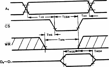
NOTE: TCSW, TWW and TWDH have been measured with either or high.
Fig. A-1 Write Timing
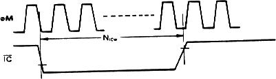
Fig. A-2 Reset Timing
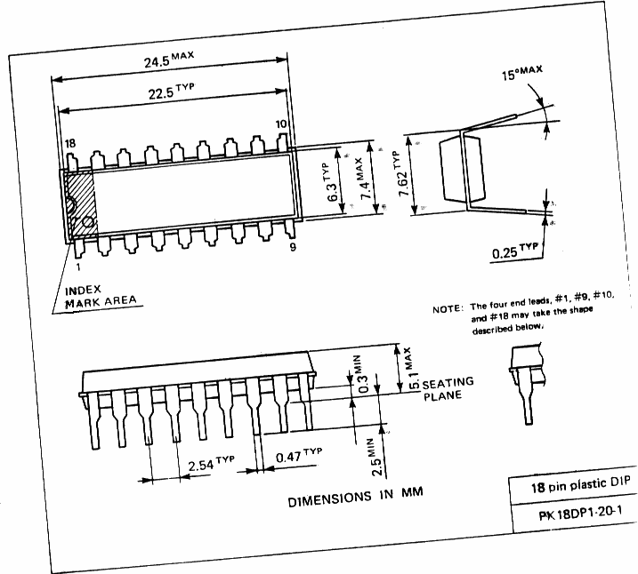
VII. OUTLINE DIMENSIONS