
Master System II RGB/S-Video Modification
Add RGB, S-Video, Composite and Audio outputs to the SMS II
Overview, by Mike Gordon
The Master System II, launched in 1990, was a cut-down version of the Master System designed to reduce manufacturing costs. Coming in at a significantly lower price point than the original SMS, the following features were removed:
Card slot
Expansion port
Power On light
Reset button
A/V output socket
The omission of an A/V socket meant that the high quality RGB output of the original Master System wasn't available to buyers of the SMS II. Only a RF output was provided. (Conversely, the Master System II sold in France retained the A/V connector but omitted the RF port.)
Almost all televisions sold in Europe now have RGB SCART connectors, and many sets sold worldwide have S-Video capability. I've devised a modification which will allow Master System II owners to take advantage of this - adding RGB, S-Video (Y/C), Composite Video, and Audio outputs.
Schematic
Constructing the RGB Board
The following parts are required :
220uF Electrolytic Capacitors x 6 (1 for Composite, 2 for Y/C (S-Video), 3 for RGB. The Composite connection is still required for Sync when RGB is used.)
10uF Electrolytic Capacitor x 1 (for the Audio connection.)
75 Ohm Resistors x 6 (again, one for each video connection as shown in the schematic.)
100 Ohm Resistor x 1 (required for switching voltage only if SCART connection is to be used - not needed otherwise.)
Cable
Veroboard (small piece around 18 tracks by 15 holes.)
Connectors (whatever is required for your equipment - SCART, S-Video, RCA, DIN etc.)
Mount the components on the Veroboard, cutting tracks as required. See the photo further down the page for an example.
As shown on the schematic, the video connections are obtained from various pins on the Master System's CXA 1145 encoder chip. You can solder wires directly to the legs of the chip - the pin numbers are printed on the Master System's motherboard, in case you're unsure.
Audio is obtained from pin 15 of the SMS's custom chip marked 315-5246, which has 64 pins close together in a zig-zag formation. (Rather than solder directly to the chip, you can instead solder to the negative leg of capacitor C31, an electrolytic capacitor just in front of the CXA 1145.)
Finally the GND and switching voltage connections can be obtained from any ground and +5v points on the board, respectively. Pins 24 and 12 respectively of the CXA 1145 are suitable.
If you're using a SCART connection, here are the appropriate pins of the plug :
| Connection | SCART pin |
| Red | 15 |
| Green | 11 |
| Blue | 7 |
| Composite/Sync In | 20 |
| RGB switching | 16 |
| Ground | 4, 17, 21 |
| Audio In | 2, 6 |

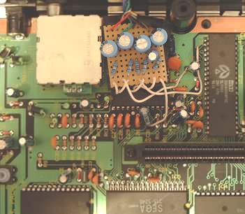
I've implemented the mod as shown above, with a captive (i.e. permanently wired) SCART cable. (I haven't included the S-Video mod since I'm unable to test this at present - my TV doesn't accept S-Video! Hence, only four 220uF capacitors and four 75 ohm resistors are included.)
The Board In Situ
Here is a photograph showing the RGB mod in place:
RGB Display
Finally, here's a screenshot from my RGB-modified Master System II.

Okay, so the improvement in quality isn't really noticeable in this picture, but trust me - the difference is huge!