|
|
ForumsSega Master System / Mark III / Game GearSG-1000 / SC-3000 / SF-7000 / OMV |
Home - Forums - Games - Scans - Maps - Cheats - Credits Music - Videos - Development - Hacks - Translations - Homebrew |
View topic - Game Gear - Light Phaser and Soft Reset
 |
| Author | Message |
|---|---|
|
Game Gear - Light Phaser and Soft Reset
|
|
I am trying to add Light Phaser support for Game Gear for Port A.
Using Mark III I/O port logic and info from this page http://www.smspower.org/Development/PeripheralPorts . I can control games from this new I/O Port including Soft Reset for games with reset routine, but just adding TH Signal doesn't seem sufficient to get Light Phaser working correctly. The Light Phaser only change Y Pos with X fixed at Right Side of Screen. For reference using Gangster Town I Can only hit letters "G", "N", "U", "." and "END". The question is this circuit should work or I am missing something? The Light Phaser works perfect on a US SMS. Except for Light Phaser support, using this circuit I get support for FM in "Turma da Mônica em: O Resgate" since with this circuit Game Gear can receive KIIL GA# and change to JAP. 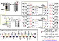
|
|
|
|
|
|
|
|
After some test and research I have found that NHL Signal is required to trigger X Pos on Screen.
Using a scope and Light Phaser on port 2 I can see this signal changing while pointing Light Phaser to TV set. The same signal can be seem on TH, but is not sufficient to get Light Phaser working. Mixing TH with NHL will not work too, but using an IC and sending TH signal though this IC I can get Light Phaser working. In attachment you can see the additional circuit to get Light Phaser working for Port 1 on Game Gear and where you can get NHL signal. I have made a video to show Light Phaser working. https://www.youtube.com/watch?v=dujxOupKjqQ 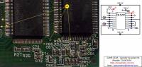
|
|
|
|
|
|
|
|
Yup the !HL signal on the VDP is required in the process also.
Very naiss ~ |
|
|
|
|
|
|
|
Hi,
I am a little confused but very interested in your research here. I had achieved Light Phaser support for Game Gear using only the TH pin - but the catch is, the ROMS had to be reprogrammed for Player 2 only. http://www.smspower.org/forums/15523-LightPhaserPlayer2HacksWasSMSProgrammingReq... so I'm a little confused in what you are attempting...is it to use the Light Phaser somehow as Player 1? Would mind posting more detail on this hack? I'm very curious. -Segasonicfan |
|
|
|
|
|
|
Yes! With this mod (hack) you will get support for Light Phaser on Port A. You can see this mod working in posted video (https://www.youtube.com/watch?v=dujxOupKjqQ). With this mod you will have access to all bits on Ports $DC and $DD which includes TH and Soft Reset for SMS Games with support, but TH can be used as input only. I have attached a schematic with complete circuit. The internal ports will be disabled while this circuit is active. You can enable internal ports just putting !KILL GA# at High State. 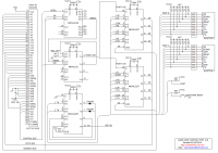
|
|
|
|
|
|
|
Wow, thanks for sharing this!!! Very cool mod and I'm so glad to know there are people with the Game Gear love out there and the skills to hack them! From what I can tell, the advantage to this circuit over the simple hack I did are: 1) You can play actual SMS games (no 2P hacked ROMs on Everdrive needed) 2) You can play 1P and 2P simultaneous SMS Light Phaser Games 3) Soft reset support I'm a little curious how the soft reset works...does the Game Gear not have a RESET pin on the ASIC? You could also reset the system via the DC-DC chip as well I think, though that isn't as safe and effective way for power cycling. Lastly, I noticed your TV appears to be PAL. Did you know about the hack I found to charge your GG TV output to PAL mode? You can do it, and play your games in 50hz and color in your case :) If using the VIletim TV board you would have to charge the xtal and do logic low on pin 7 of the chroma encoder of course. -Segasonicfan |
|
|
|
|
|
Last edited by Esrael on Sun Nov 20, 2016 5:50 pm; edited 1 time in total |
Software Reset is done at software side, if your game does not have a software reset routine nothing occur when you set a bit #04 of $DD port to 0. Edit: ResetButton -> http://www.smspower.org/Development/ResetButton and Port $DD -> http://www.smspower.org/Development/PeripheralPorts#portdd
Here the color system is PAL-M running at 60Hz, but the image in TV set is in BW because this game gear is using only simple DAC with resistors. About colors, thanks for the information, but i have made custom PAL-M encoder using Tim Worthington digital to analog RGB, custom circuit using CXA1645P to get composite and a transistorized circuit to get YPbPr output. Color Decoder/Encoder -> http://esraelneto.com.br/hardware/gg_saida_tv.php Game Gear on SMS Case -> http://esraelneto.com.br/hardware/gg_consolizado.php Edit: 20/11/2016 - Fixed broken links. All credits and sources are given. |
|
|
|
|
|
|
|
Updated schematic.
This new circuit only uses bits 4 to 7 of port $DD leaving internal ports enabled. Bits 4 and 5 are optional, if you only want Light Phaser support, They are used for Software Reset and Cont respectively. 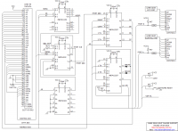
|
|
|
|
|
|
|
what do you mean by this? What is the "Cont" function and where does it connect on the board? I also see "KIIL GA#" is still labelled in the new version, but now you are saying it is unused since the internal controls work in this version without pulling it high. Is this true? Or do I need to pull KIIL GA# still? Where does it connect to on the GG board? Thanks for the update! and you site is AMAZING. I really envy your knowledge of electronics. -Segasonicfan |
|
|
|
|
|
|
The !Cont can be used in SMS Cartridge, but i don´t remember seeing any game using this signal. During assembly of this project I have found a bug, which causes SMS games Always booting in Jap Mode, which i have fixed by disabling this circuit during region check by games. I have attached new circuit with Region Check fix If you want to know the full details of project using this I have published in my page a Game Gear consolized with FM, Light Phaser support, 3D input and built-in ROM Game with auto select Slots by priority (Game Gear, SMS and Internal ROM) http://www.neto-games.com.br/hardware/gg_consolizado_v2.php ![gg_porta_dd[1].png](files/thumbs/t_gg_porta_dd1_825.png)
|
|
|
|
|
|
|
|
Hi Neto, thank you so much for the reply :)
I saw that link before and have been admiring your work. It is amazing. I was showing it to a friend (so much soldering!!) I want to undertake a similar project as yours but with minor changes. That is why I would love to understand your circuit as best as possible. It looks like !CONT is only for SG-1000 and SG-3000 cart support, according to Charles McDonald here: http://www.smspower.org/forums/6607-CartridgePinoutDiagram "CONT is a generic input bit that can be read from port $DD of the I/O chip (or in hardware without it, it's mapped to one of the PPI input ports). But no cartridges use it." so my Questions are: 1) If I do not want !CONT or RESET available, can I leave out D5 and D4 from the 74LS257? 2) !HL is generated by the 74LS257 and then soldered to the VDP, correct? This means that the mod is only possible on 2-ASIC Game Gears (I think) because !HL is not available in 1-ASIC. Is that correct? 3) What does the circle symbol by the inputs mean in your schematic (see attached picture)? and less important: 4) is the BC558 used as a switch only? 5) why are there 4k7 resistors for some of the logic high inputs? 6) !KBSEL is generated for your FM circuit, correct? or does it go to the SMS cart slot? I cannot find where this pin corresponds to ont he SMS (and I looked here: http://www.smspower.org/maxim/Documents/Pinouts) Thank you so much for your time! I greatly appreciate your work. -Segasonicfan 
|
|
|
|
|
|
|
1-) Yes, but Reset can be used for SMS games. 2-) Yes, this circuit only works in Two Asic Version GG. 3-) The circle is just for pins ids of ICs 5, 10, 15..... 4-) Yes, the transistor is used during game region check to disable this circuit. 5-) The, resistors is used to set bits to 1. 6-) !KBSel is used by FM and by this circuit and can be used in SMS cart if you want. |
|
|
|
|
|
|
|
Thank you so much for the reply!! It was very nice of you to answer all my questions.
The pullup resistors on the output signals make sense, though it seems the 2x other 4k7 could be shorted for the logic chips since VCC = bit 1 right? Im going to get working on building this, thank you! -Segasonicfan |
|
|
|
|