|
|
ForumsSega Master System / Mark III / Game GearSG-1000 / SC-3000 / SF-7000 / OMV |
Home - Forums - Games - Scans - Maps - Cheats - Credits Music - Videos - Development - Hacks - Translations - Homebrew |
View topic - Sega SC-3000 Component Video Daughterboard for PAL SC-3000
 |
| Author | Message |
|---|---|
|
Sega SC-3000 Component Video Daughterboard for PAL SC-3000
|
|
Hi All
Frank_fjs asked about this in the Megacart thread - I assume this is was referring to. The other project I've had going on in the background is the component video replacement daughterboard for the PAL Sega 4095 composite video daughterboard in the SC-3000. This takes the Y / R-Y / B-Y signals from the TMS9929A, removes the back porch pulses on R-Y and B-Y, and (I think) correctly scales everything to give you a Y/ Pb / Pr component video output. I have a PCB for it and the output looks great. Unfortunately I didn't do a proper test fit inside an actual SC-3000 case, so the boards I have catch slightly on the RF modulator, and the output side is a little close to the heat sink. You can still jam it in there, but it isn't ideal. Here it is: 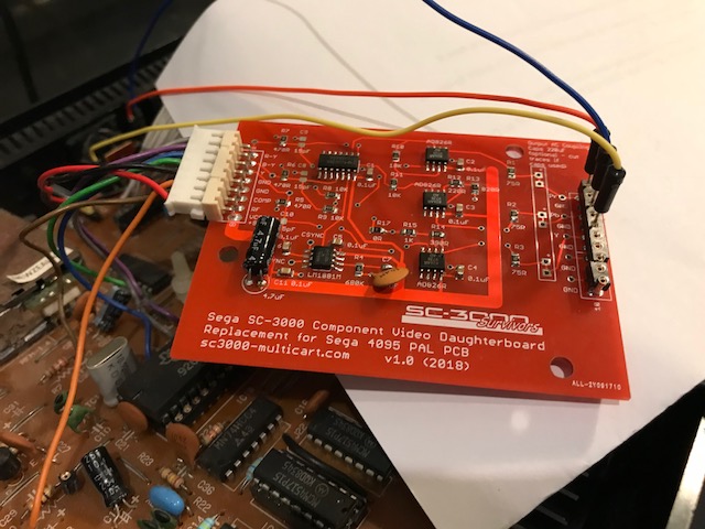
I have a redesigned PCB which I haven't had time to send off for manufacture that fixes the layout, and also has a few other tweaks like a point for a capacitor for the SG-1000 sound if you use it in one of those, and a loop back to the composite output pin so that the Y channel can be output through the 5 pin DIN at the rear of the SC-3000. Is there any interest in this if I make a few up? I'll probably do 10 or so at about $40USD + shipping ($5USD to NZ, $7.50USD to Aussie, $12.50USD to the rest of the world). PM me if you're interested or contact me through the http://sc3000-multicart.com/contactus.htm page. Just be aware I'm pretty busy with real life, and as much as I love these Sega projects it might take me a little while to get back to you, sorry :) It is pretty easy to install if you are confident enough to open up your SC-3000 case. It is a plug and play replacement for the 4095 daughterboard. Just unclip the 4095 and plug in the component video mod. You have to make your own cable up. You can wire it in however you like - mount RCA jacks on the SC-3000, or make a small cut and poke a cable through, or if you make two small solder points on the SC-3000 motherboard, you can route everything through the existing 5 pin DIN on the rear of the SC-3000 and have a 4 x RCA to 5 pin DIN cable which has both the sound and the component video output. You can see the output from the PCB in the Megacart video I posted. As you can see the colours are good, and the text in the test pattern section has minimal bleed with the different colour combinations. The entire video from the SC-3000 uses this PCB, but the pattern starts around 5:45 if you want to see really fine detail. The fine print: 1. PAL SC-3000 only (as sold in NZ and Australia). It will not work in a Japanese SC-3000 as it requires the Y / R-Y / B-Y outputs. You could probably wire into a Yeno if you really wanted to, but that already has RGB output so not sure why you would. 2. Your mileage will vary depending on your TV. It is still a 288p signal so in general the older your TV, the more likely it is to work with this. If your TV does a good job on the normal composite output from the SC-3000 then there is a good chance it will work well. I didn't have much luck with 100Hz 'digital / double scan' CRTs when I was testing. But I have a 29" Panasonic CRT from about 2003 which works great, and two LCD screens from early to mid 2000s which work great. My 2011 Panasonic Plasma works, but it applies more digital filtering to the picture so looked a little odd. 3. As usual, all the risk is up to you if you want to try one of these :) I have used mine for hundreds of hours without causing any issues to the TVs but no responsibility accepted for any real or imagined issues with your TV or SC-3000. Here is the full development thread from the NZ Classic Computers Forum https://www.classic-computers.org.nz/forums/viewtopic.php?f=11&t=960&sta... And here is an earlier SMSPower thread where I discussed it. I assume this is what Frank_fjs was referring to. http://www.smspower.org/forums/16515-TMS9929AVideoOutputLevels Cheers |
|
|
|
|
|
|
|
Thank you!
I'm interested in developing a simple RGBS to component converter which is why I asked for more details. I'm looking at implementing mine with a TA1287, THS7374 and LM1881. Idea being to buffer and attenuate the incoming RGB, clean up and standardise the sync and output the component signal. I just finished with an RGBS to composite and s-video converter based on the Sony CXA2075. It's working well so want to come up with a component converter to cover all bases. |
|
|
|
|
|
|
Cool :) I've had a skim back through a couple of your recent threads. Looks like you've been busy too :) That TA1287 looks interesting. Do you have a clean 9v feed anywhere to power it? The two main issues with getting any sort of video out of a TMS9929A are: 1. Removing the pulses on the R-Y and B-Y back porch 2. Scaling Y / R-Y / B-Y to the correct colour space. If you are starting from an RGB source then you only have the scaling issue to deal with, and if the TA1287 has that covered, then great :) Charles Poynton's notes are a great reference on scaling between different colour spaces if you need to do it manually. https://poynton.ca/notes/colour_and_gamma/ColorFAQ.html https://poynton.ca/notes/colour_and_gamma/ColorFAQ.html#RTFToC28 The LM1881 is great for detecting the sync on a video signal and then telling the rest of your circuit to do something during sync. What do you need to do with the sync on the incoming signal? You really only need it on the Y channel for component. I tried a THS7374 (and a THS7314 and THS7316) during development of this PCB. They are nice chips with built in 5th / 6th order butterworth filters, and the THS7374 allows you to optionally enable / disable the filter from memory. I was trying those because one of my TVs shows light vertical stripes in areas of solid colour and modders for other consoles had reported success with using the THSXXXX chips for that (a common theory is this effect is due to high frequency IC switching noise embedded in the incoming video signal from inside the console). It is interesting looking at oscilloscope output of the different signals (TMS9929A output, opamp output, THS7314/16, THS7374 with / without filter, adding / removing additional 15pF filter capacitors etc.) I could see the subtle differences to the signals with each change, which is really cool. But I was never able to 'see' a repeating signal in the scope trace that would result in the banding, and none of the techniques made any difference to it. I also couldn't honestly tell the difference between the different circuits visually which is why I settled on just the AD826 / 828 opamps (AD828 were slightly cheaper and visually the result seems the same to me). In the end I decided that the banding might just be related to how the digitizer on this one TV works. Good luck. The display related projects are a lot of fun :) If you don't have an oscilloscope already, then they are an awesome and necessary tool for debugging the circuits. I couldn't have done it without my trusty little Rigol 1052. I'd love to get one of the newer Rigol 1054z scopes though as 4 channels would have made life sooooo much easier than 2 channels. Maybe for my birthday :) Cheers |
|
|
|
|
|
|
|
My oscilloscope is ancient! It's from the late 70s and I don't have probes for it but it does display an inbuilt test signal just fine.
I was thinking: RGB in to pots wired as a voltage divider, which will then lead to a THS7314. 75R in series on the way out for impedance and then to the TA1287 for the conversion. Hopefully leaving me with correct YUV output. Sync in to LM1881 and straight to Y output. Take 5V from scart and step up to 9V to power the TA1287. Drop the 5V via resistor to 3.5V for the TA1287 conversion setting. Perhaps include a DC power jack with a switch to enable/disable external power option. Sounds good in theory, have yet to test if it works. Just waiting on parts. All going well I'll fabricate a PCB. |
|
|
|
|
|
|
|
Hi All
I sent off a new Sega SC-3000 component video pcb design with the Megacart boards. Photo attached. I haven’t assembled and tested it yet so fingers crossed I didn’t break anything. The design is technically the same and in fact the surface mount components haven’t moved so I could use the same stencil I made the first time. Changes are 1. Input connector lower to avoid the SC-3000 RF modulator 2. Output connector lower to avoid plastic support pin for top half of SC3000 case. 3. Loopback from Y input to Comp output. That means that you can still get a black and white signal out of the standard SC3000 5 pin DIN output when you plug it into the composite video input on your TV as a quick test. It also means one less solder point and no trace cutting on SC 3000 motherboard if you want to route component video out the 5 pin DIN via the two unused pins (most PAL SC3000s have two unused pins with composite, sound, and ground on the other three pins - there are little solder jumpers and solder points on the motherboard you can wire the Pb and Pr output signals to for the unused pins). The comp pin on the input connector runs through a buffer transistor and a voltage divider on the SC3000 motherboard to correctly scale the 1.44v p-p Y signal from the TMS9929a back to 1v p-p so the loopback works perfectly. I have a jumper on there so that can be disabled if necessary and then you use the Y output at the RHS of the board. 4. Solder point to connect to pin 4 on RF modulator of SG1000 (and then through a 10uF capacitor) if you want to replace the composite daughterboard in a PAL SG1000. You then need to be able to route the sound out. Pin 4 of the RF modulator is a direct feed from the sound chip on a SG1000 5. Larger 4.4mm diameter mounting holes instead of 4mm. The original Sega boards used 4mm holes and they are just too tight if you ever want to remove the daughterboard from the plastic mounting pins. I did a quick test fit of the empty PCB and it looks like it should fit properly this time. Fingers crossed. Frank - how are you getting on with your converter? Have your parts arrived yet? Cheers 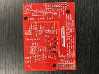
|
|
|
|
|
|
|
|
Hey there,
Expecting parts to arrive any day now. Have a PCB designed in software but won't commit to production until I test everything first. In the meantime I've tweaked my RGBS to composite/s-video board with good results. Never had an issue with the s-video side of things, it looks great, nothing to improve. Initially the composite video output was a bit rough but I've managed to step up the quality considerably via better PCB trace design, separated ground planes for power and video, adjusted the voltage to the oscillator and a smoothing capacitor for the oscillator output. It looks great now, tiny bit of dot crawl most noticeable on red colours but if I didn't point it out you probably wouldn't notice it. This is to accompany an arcade supergun that I've developed. |
|
|
|
|
|
|
|
Parts came in but I'm not winning.
Can get a black & white image but no colour info coming through. |
|
|
|
|
|
|
Some thoughts: A black and white image suggests maybe just the Y channel is being picked up by TV. Do you have the voltage set correctly on the mode pin of the TA1287? Maybe it is just passing the RGB through instead of converting to YUV? Any shorts / breaks in test rig? Any channels blown on your THS7314? I have blown individual channels on those during development Does the TV you are using require sync on all three Y / Pb / Pr channels? I wouldn’t have thought so but maybe Is the YUV output actually equivalent to Y / Pb / Pr component? Or are you generating an incompatible signal? Eg Y / R-Y / B-Y is different to Y / Pb / Pr as the R-Y and B-Y signals must be scaled. The YUV PAL / NTSC output might be the wrong colour encoding for what you want although I would have thought you would get bad colours rather than black and white. I don't have enough of the different systems in my head right now, but here is a simplified overview of different colour difference systems https://wolfcrow.com/blog/whats-the-difference-between-yuv-yiq-ypbpr-and-ycbcr/ Update - Also, do you have another buffer amplifier / driver after the TA1287? If you want to drive component inputs after that, you may need another 2x amplifier with 75 ohm resistors to keep the output voltage in correct range. I also found having a test pattern to be very useful. eg. when using with something like a Sega SC-3000, you can write a Basic program to output specific vertical bands of colour. That way when you look at your scope output you have exact expect voltages and waveforms that you can check against. I believe you can get hardware versions of those test pattern generators too, but no idea where to find one or how expensive they are. Good luck :) |
|
|
|
|
|
|
|
I didn't actually hook up the amps was just testing the main Toshiba IC. All I did was feed it RGB via decoupling caps, fed sync to Y. Experimented with different voltages on the matrix pin.
I believe all I'm seeing is the composite video signal from the sync line which runs to Y out. I tried with pure sync and I can barely see an image at all. Maybe I do need the RGB amp to see anything useful. I don't know may just put this project on hold for now. |
|
|
|
|