|
|
ForumsSega Master System / Mark III / Game GearSG-1000 / SC-3000 / SF-7000 / OMV |
Home - Forums - Games - Scans - Maps - Cheats - Credits Music - Videos - Development - Hacks - Translations - Homebrew |
View topic - Sega SC-3000 Megacart - detecting I/O port mapping on SG-1000 / Mark III
 |
| Author | Message |
|---|---|
|
Sega SC-3000 Megacart - detecting I/O port mapping on SG-1000 / Mark III
|
|
Hi All
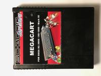
Here's an interesting little hardware hack if you're building devices to connect to the cartridge port on the SC-3000 / SG-1000 / Mark III using I/O Port mapping. Long time readers might remember when I developed the Sega SC-3000 Multicart back in 2011 / 2012 http://www.smspower.org/forums/13351-SC3000SG1000MulticartWithCartAndTapeGames The short story is that the Mk II Multicart has 70+ pieces of tape software on a cartridge, along with space for another 32 SG-1000 ROMs. I've been building the odd one over the past few years for anyone that tracks me down and convinces me they love the SC-3000 :) Last year, I ran out of PCBs so decided to try to fix a couple of things I wasn't happy with on the original design, resulting in the new Survivors Megacart (see photo below). It has twice the storage (so fits another 96 SG-1000 ROMs along with the tape software), and it now works on a SG-1000 / SG-1000 II, and should work with a Mark III. The Multicart paging system is I/O port mapped and it relies on the /IOW signal passed out pin B8 on the SC-3000 cartridge port. But the SG-1000 / II / Mark III have pin B8 disconnected, and don't pass the Z80 /IORQ signal out the cartridge port. So there was no obvious way to get that design to work with those consoles. Well... there was a way. Back in 2011 I asked Charles MacDonald if he thought the following rule would work to detect an I/O port write: If the Z80 /WR is low and /MREQ is high, then it is a I/O Port Write, not a memory access I think his reply was along the lines of "That's sneaky... but it might work". I didn't have time to try it back then but I dusted it off this time around, and it works. The SG-1000 / Mark III pass both the Z80 /MREQ and /WR signals, so the following circuit works on both SC-3000 and SG-1000 to detect IO Port Writes: (Note - I don't have a Mark III to test with, but it should work there too. SG-1000 / II works great) 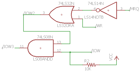
For anyone who is interested you can read a more detailed overview and explanation here: http://sc3000-multicart.com/megacart.htm#howitworks The important thing to understand with the above circuit is that on a SC-3000, /WR is actually Z80 /WR strobed with /MREQ, but on a SG-1000 /WR is just Z80 /WR. And on a SG-1000, the /IOW pin B8 signal is not connected. So the top half of the circuit detects IO Port writes on a SG-1000 and the bottom half detects I/O port writes on a SC-3000. Actually - if you read further down that page you will also see some notes on how I finally got the reset switch working. It now gates $FF onto the data bus while the switch is depressed. That both resets the Megacart paging system to the menu block, and forces the Z80 to execute RST $38 until the reset switch is released, at which point it executes the boot menu startup code. As usual, most of the fun was in designing and building the thing, so I've documented this technique just in case anyone else is silly enough to try to build something like it :) Any comments or thoughts are welcome. Any real electrical engineers in the audience please feel free to tell me why this is a terrible idea. But it seems to work pretty well. Cheers 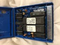
|
|
|
|
|
|
|
|
Very cool indeed!
I missed out on your original cart. If you have a good memory you'll remember that I had an SC-3000 with a damaged cartridge port for which you helped me source a replacement. Thanks! I'd love to be a Mark III tester. Send me a PM if you have any units for sale. |
|
|
|
|
|
|
| As long as your reset drives FF on the bus only on reads you'll do fine, but if it also goes there on writes too you're killing the Z80 and whatever you use to drive FF on the bus. | |
|
|
|
|
|
I ended up using a similar scheme for the MkIII to SMS adapter I'm working on. On a master system you have /IOREQ coming out to the cart connector (on an export system anyway). That's also the case on a game gear with a gear master adapter. BUT... on a Mega drive/Genesis using a power base converter that pin wasn't present. After a bit of a rethink and some trial and error i essentially came up with the same thing, which seems to work well. |
|
|
|
|
|
Last edited by honestbob on Sat May 19, 2018 11:48 am; edited 1 time in total |
Interesting. I have a second 74LS373 (ie. distinct from the paging latch) driving the data bus when the switch is depressed (see attached image - it is driven by a double inversion of the switch depress which is active low //SW). While the switch is depressed, the 27C160 EPROMs and static RAM on the multicart are disabled, so this reset latch should be the only external driver of the data bus. But it will continue to drive the data bus as long as the switch is depressed. I thought about what would happen during a write situation, but aside from the instant you activate the 74LS373 reset latch, when would a write situation occur? From that point on the SC-3000 is only going to see a RST $38 instruction. I would have thought that would cause internal Z80 registers and the address bus to update, but I wouldn't have thought the Z80 would drive the data bus again until the switch is released and the EPROM / RAM So my hope was at best there would be only nano seconds or micro seconds of contention as the switch is pressed / released. Thoughts? Or am I missing something obvious about the Z80 behaviour? Ah... you are probably correct... as part of the RST $38 instruction the Z80 performs a push of the current program counter onto the stack. I didn't consider that... and it does it over and over and over so long as the button is depressed. Well... I guess I just need to try pressing the reset switch several hundred more times to see what sort of issues appear. My SC-3000 test rig has been through a lot and I haven't managed to kill it yet. Fingers crossed :) 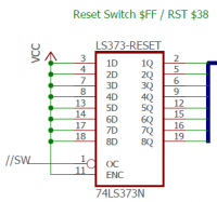
|
|
|
|
|
|
|
Very cool. I'm glad to know someone else found this technique to be reliable. It is one of those situations where necessity drives you to try something the system designers hadn't anticipated. |
|
|
|
|
|
|
Hi Frank - great to hear from you. If I recall correctly, you may have been a bit too enthusiastic in following some instructions in a video I reposted on how to clean the cartridge slot ;) I'm glad you got everything up an running again in the end. I've emailed you (hope your email address is still the same) Cheers |
|
|
|
|
|
|
|
The reset switch needs to be gated with ROM !OE and !CE, it will make sure you don't drive the bus when CPU is writing or system RAM is being read. Bus fights will cause damage in the long term and could even do it in short term.
If you connected output of one logic chip that drives high with another that drives low you'll see how both of the chips get really hot and pretty shortly after stop working. The same thing will happen to the latch and CPU or RAM in the right conditions. Bus fights are never safe. |
|
|
|
|
|
|
Thanks for that. That's a shame I didn't pick up the possible contention issue (I didn't think about the RST $38 writing the program counter to the data bus for the push to stack memory). Ideally I would have liked to avoid that (I did avoid the ROM / RAM contention by disabling those - so it is just the Z80 contention that might be an issue). However I'm going to struggle to redesign things at this point. So unfortunately the best thing I can do is probably to include the above advice as a warning and try a couple of things like holding down the switch for a few minutes / pressing it another thousand times etc. and see what breaks on my test rig. I do have a cheap infra red temp gauge so I will see if that shows anything interesting on the Z80 or Megacart LS373. It is of course an option for a user to turn the SC-3000 / console off and then on again instead of using the reset button, although that might just result in a different type of 'wear and tear' on the system. |
|
|
|
|
|
|
|
Hi All
Here's a video I took last night if you want a better idea of what the SC-3000 Survivors Megacart is like to use. You can see how much more I've packed onto the PCB in the opening shot with the Megacart beside the second Mk II Multicart I ever assembled (I think Bock has number #001). Cheers |
|
|
|
|
|
|
|
As per the above discussion with TmEE, I gave the Megacart reset switch a stress test comprised of:
1. 1000 individual presses of the reset switch 2. Three instances of depressing the reset switch and holding it down for 20 seconds each time. The Z80 and Megacart came through that ok, and I have probably clicked the reset button a thousand other times while developing the Megacart. So that's about the best I can do. I wish I had designed the reset switch circuit slightly differently, but it appears to work well and as yet I haven't been able to force it to cause damage to the Z80 or Megacart. So that is 'good enough'. Note - I have a test routine I run on all the Megacarts which has random bytes spread through 127 of the 128 blocks of 32KB on the Megacart. Each 32KB block has a header field saying which block it is and a (very) simple checksum. This 32KB block is then copied to the 32KB RAM on the Megacart and byte compared with the ROM image and also the header field and checksum are validated. So that checks every IC in the Megacart as well as basic Z80 operation. I had that test running that for an hour after the stress test to check that all the hardware is working correctly, and everything still looks good. |
|
|
|
|
|
|
| If you're not gonna do it right then at least add some current limit resistors in series with the latch output. 220/330/470 ohm will be adequate. | |
|
|
|
|
|
Thanks for the suggestion, much appreciated. I hadn't thought of that. It certainly isn't an issue of not wanting to do it right or not caring. This oversight really annoys me. It is more that I already have a pile of PCBs and I don't have the mental energy to make the change right now and test that out :) I will certainly look at it again if I do another PCB run later on. In terms of a later redesign, I don't think I could fit another 8 resistors in there as it is a through hole design and it only just fits inside a SG-1000 cartridge case as it is (see photo earlier in thread). So my preference would be to fix it properly if I was going to do anything. I *almost* have enough components to pull off the 'do it right' approach of disabling the $FF reset latch during /WR. I can do that by making 4 cuts to the PCB traces and 4 jumper wires and that will fix the bus contention when the switch is depressed. But I also think it might break my reset switch operation if the switch is released during /WR because the paging latch would then latch whatever program counter value the Z80 has put on the data bus during the RST $38 instruction. I can fix that, but not without wider changes to the circuit and maybe another OR gate (I've used up the two LS32s on the cart already). That is down to my poor original choice back in 2011 of a LS373 as the paging latch instead of something like a LS273 that has a seperate reset line and resets to zeros (unlike the 373 which doesn't have a reset line and powers on to all ones due to internal pull up resistors). But I couldn't change that without breaking all the converted tape software which expects to find things in a specific block of the Megacart / Multicart (the menu system is still backward compatible with the original multicart). Side note - if there is a similar TTL style part to the LS273 that has a reset line and resets to all ONEs instead of zeros, I'd love to know about it. But I couldn't find any. So it will have to wait for a future redesign when I'm a bit fresher and have more time to play around with some alternatives. Cheers |
|
|
|
|
|
|
| Unrelated... Any info on the RGB to YUV converter? | |
|
|
|
|
|
Here you go :) http://www.smspower.org/forums/17090-SegaSC3000ComponentVideoDaughterboardForPAL... |
|
|
|
|
|
|
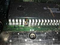
You can do similar thing as seen in the photo I attached. A bit of effort but won't require any new realestate.
|
|
|
|
|
|
|
Thanks - that's a nice little hack. I would probably have to solder that 373 into place instead of using a socket as there wouldn't be enough space otherwise. I might cut up a cart and see how hard it is to do and whether it all fits once I have jammed 8 resistors in vertically like that. (Space is tight both beside the IC and also for clearance to the lid of the cartridge case). My preference is still to fix it properly in a future revision. I just need a couple more OR / NOT gates or to change something else earlier in the circuit... I'll have a think about it. And I'll give the reset switch on the existing PCB another couple of thousand presses to see if anything bad happens too :) |
|
|
|
|
|
|
|
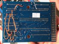
Ok, I’ve figured out how to fix the reset switch properly using only the chips I have on the PCB. Check out the attached schematic and photo (it only needs 4 jumper wires but I tried something else first).
The only downside is the switch is not fully debounced any more because I have to use the LS14 Schmitt Trigger NOT gates elsewhere in the circuit (the NOT gates used to hang off the end of the SW output). But the RC circuit on the switch seems to work well even without the LS14. I tested it about 20 or 30 times and it worked each time on both sc3000 and sg1000 II This circuit should ensure: The LS373 paging latch only latches the data lines when switch is depressed and during /RD The reset LS373 latch only gates $FF onto the data bus when switch is depressed and during /RD ROM and RAM are disabled at the same time the reset latch is gating $FF onto the data bus The reset LS373 latch deactivation and ROM/RAM reactivation are delayed slightly from the point the paging 373 latches the data, so $FF should always be on the data bus when the paging 373 latches the data. So there we go. Contention on Z80 write solved :) In other news, I still haven’t been able to see any damage after another few hundred reset switch presses on the original design. But I can certainly use this revised circuit on a future PCB. Thanks to TmEE for encouraging me to try a bit harder :) Cheers 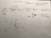
|
|
|
|
|
|
|
|
Very nice ~
Another thing is that you shouldn't use tin plated edge contacts, they will wear out the cartslots quicker and not just due to thick and uneven surface but also from galvanic corrosion (slots are gold plated so mating surfaces also need to be gold plated). This is a more longer term (unless one lives in relatively humid or salty environment) but something to look out for. The connector seems not to be the most easiest thing to find so it would be nice if its life gets extended as much as possible. |
|
|
|
|
|
|
Thanks. I actually tried to get immersion gold coating on the fingers the last run I did. I used AllPCB. They did a nice job and were quick, had an easy order process with customization options, and were fast and inexpensive. But it looks like I can't specify immersion gold without having the entire board finished with immersion gold. I ticked Golden Finger Beveling last time, but there is a comment on the order page that says "Same treatment with chosen surface finish" and although the edge was nicely beveled, it still had the HASL finish. eg. Here is their quote page: http://www.allpcb.com/online_quote.html?hidLength=98&hidWidth=73&num=50&... The cost for full immersion gold finish is ok, but I don't know whether I can use normal solder with that if the entire board comes with immersion gold finish. Until now I have always used 60 tin / 40 lead solder with HASL with Lead finish and it is nice and easy to solder and seems reliable. Could I keep using the same solder if I selected the immersion gold surface finish the next run? What about the thickness 1u" vs 2u"? I'd appreciate some advice. |
|
|
|
|
|
|
|
You get either full gold or full solder plating. Full gold solders better than solder plated, both manual soldering and solder paste + reflow. No oxides to get in the way or complications of mixed solder types (you are not likely to use same solder as the plating).
I personally use EasyEDA/JLCPCB, really great quality and very nice price, especially on volume orders. 1oz is fine for digital electronics stuff, plus you can have 0.15mm tracks and spacings. 2oz copper is better for things that carry power such as power supplies and amplifiers but you don't get as fine tracks or spacings, plus it costs more and takes longer to make. |
|
|
|
|
|
|
For surface finishes these days your likely to have one of three. The first is lead free (some places still do leaded too) hot air leveled.. which is the solder coated you have there. Immersion silver is another and immersion gold. Hot air leveled is fine but as mentioned you dont know the exact mix thats being used so you can run into problems with differences between whats on the board and the solder your using. It can also have an uneven thickness and is not so great for card edge fingers. Immersion silver always dead flat and uniform and is fine for general assembly if used fairly quickly and kept dry prior to assembly. It will tranish making assembly difficult if left too long or kept in humid environments. Also not too useful on card edge fingers due to tarnishing. Immersion gold has no oxodation issues and generally seems to be the choice of surface finish these days. Great shelf life.. good solderability and flat and uniform thickness. Where the 1u and 2u comes into play is with hard gold. Thats the thickness of the gold. Some places use mircons and others use micro inches. Hard gold, or electro plated gold, is normally used where physical contact is made between 2 parts. Connectors, sockets, pins, keypads etc. Its much thicker and alot harder wearing than immersion gold. This is what you will find on typical card edge fingers. It will probably add a bit of cost as its a separate process to the rest of the surface finish. It also requires all of the fingers to be electrically connected to have them electroplated. They normally do that outside of the board edge and route the connections away during final routing. You can tell the difference as elwctroplated gold has a deeper colour and is shiny. Immersion gold is usually flat and more of a yellow colour. So.. immersion gold would be better for the connector than hot air level but hard gold would be better again and give the best service life. |
|
|
|
|
|
|
|
Thanks TmEE and wasup for your comments, much appreciated.
I decided to run with the 2u" immersion gold option from AllPCB. Hopefully it is thick / hard enough it won't be scraped off by the SC-3000 cartridge slot pins. We'll see. I couldn't find any simple options for doing a second hard gold plating pass just on the edge connector, so I assume the fingers will come back with 2u" immersion as well. Just as a side note, the fingers on a multicart I assembled back in 2011 are looking quite oxidised now where the SC-3000 edge connector has rubbed on it (HASL with lead finish). It still works fine, but the PCB connectors could use a good clean as you have to jiggle it a bit before it works properly. But that is true of most of my original carts too. I also sent off my revised component video PCB. So I should have something new to play with in another week or so. If nothing else, the gold should look nice and sparkly :) |
|
|
|
|
|
|
|
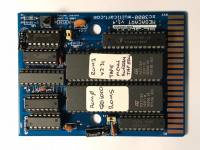
Hi All
The latest Megacart PCB arrived incorporating the revised reset switch circuit. I used AllPCB like last time as I was familiar with their order process. Gold finish this time instead of HASL. I went with the 2u” finish which was more expensive than 1u” but hopefully will last longer on the card edge as it isn’t hardened gold. The card edge seems to have held up well after half a dozen insertion / removals from the SC3000. It seems to have fewer scratches than the HASL boards. It was fine to hand solder too. Photos are attached. I will test it out a bit more over the next few days then make up a few boards. Thanks again for all the suggestions. Cheers. 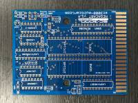
|
|
|
|
|
|
|
|
Very nice !
You should bevel the edge like all other cartridges and edge connectors, much less strain on the slot. The PCB place should have an option for that at no extra cost (at least that's how things work on JLCPCB). |
|
|
|
|
|
|
Thanks :) Yes, the edge is beveled. It is a reasonably low cost option at AllPCB. The JLCPCB pricing looked slightly lower than AllPCB for similar options. But I found the AllPCB order system more straightforward for the configuration I wanted. In particular I wasn’t sure whether JLCPCB was going to send me nicely routed individual pieces or panels which I had to snap apart myself. Not a major but I like clean edges :) The EasyEDA system looks very good for home brew work. I only skimmed the site but it looks like they effectively give you an online PCB design system (or you can upload existing designs from other packages) which you can them easily send off for manufacture. Is that right? How is their PCB design system to use? When I first started I used ExpressPCB which was a similar idea. They provided an easy to use Windows software downloadable PCB design system. That was great for a beginner. Easy to use and it behaved how you would expect a drawing program to work. You could then upload your design directly from it to manufacturing. That was where the problem was. Because it was a US company the prices were far more expensive. So I found a Thai (I think) firm, Futurlec, who would take the ExpressPCB files. I did two runs there then learnt how to use EagleCAD back in 2012. That has a much steeper learning curve and is not intuitive (although it is a lot more flexible, and still freeish for small PCBs). But I had to relearn how to use it again this time because I hadn’t used it in a few years. Things that should be simple to do just aren’t. Not too bad when you are using it regularly but hard to remember when you aren’t. |
|
|
|
|
|
|
|
I don't use their PCB software so I have no clue how it is. I do like the gerber preview they got, it gives a fairly good preview of what you get in your hands.
When I ordered 600 boards or 100 or any other number I got just that, a box full of individual boards. I haven't done any panelizing stuff, but it is possible and you can always ask for details from their support, they answer pretty quickly. |
|
|
|
|