| Author |
Message |
- Joined: 29 Sep 2018
- Posts: 6
|
SMS 2 no cartridge loading (SOLVED)
 Posted: Sat Sep 29, 2018 8:33 pm Posted: Sat Sep 29, 2018 8:33 pm
Last edited by km1kze on Tue Oct 02, 2018 8:31 am; edited 1 time in total
|
Hi people,
I have a SMS 2 that stayed in a box for some years and now is not working anymore... Before I store it, worked with every game that I had. Now is just stuck at the SEGA screen from beginning and it has no effect if I put a game inside (games are working with a SMS 1 that I have). The screen blinks black for a fraction of a second after some seconds of SEGA logo (maybe some kind of restart loop?).
I tried to adjust the pins from the cartridge slot and nothing changed.
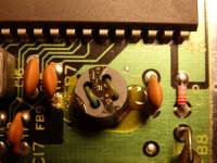
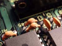
The board seems fine, nothing odd inside except this FB7 thingy located in the bottom right corner of the board (please see attachment)
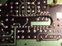
And also on the bottom of the board, under the SONY chip there is a connection wire from pin1 to a C39 capacitor.
Did someone experienced this problem? If the cleaning of the cartridge pins is not the issue, what can cause this? I remind that this console worked without problems last time and it was stored covered
Please help me to resolve this problem, Thank you
|
| |
 
|
- Joined: 14 Mar 2013
- Posts: 62
- Location: Belgium
|
Posted: Sun Sep 30, 2018 9:35 pm
|
FB is ferrite bead, seems like it's just glued on.
I have the same bodge wire under my SMS2. Guess it's a connection they forgot to make on the PCB and had to add a wire.
If it's been a few years, then it might be a capacitor issue.
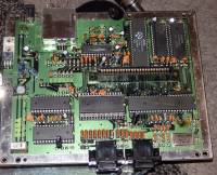
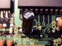
C41 (blue cap to the left) looks a bit bulged ? So does C18 behind controller 2. Might just be the pictures that makes it look like that.
You could also check the 5VDC voltage regulator (7805 IC) to see if it still outputs 5V.
|
| |

|
- Joined: 14 Aug 2000
- Posts: 742
- Location: Adelaide, Australia
|
SMS 2 no cartridge loading
Posted: Mon Oct 01, 2018 9:01 am
|
I don't think it's an issue with the cartridge connector and it's best not to manipulate these pins because that can create contact issues.
Do you have the means to measure the voltages? Checking that the regulator is outputting 5 voltage is the first thing I would do.
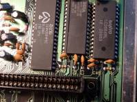
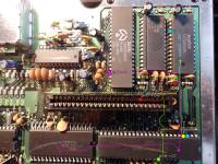
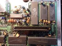
When the console is turned on, do any of the chips get hot when you touch them with your finger? If any of the chips, like the Sanyo LC3664 SRAM chip in the top right hand corner of the board for example, are getting super hot, that means they're dead.
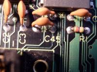
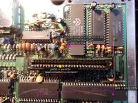
Looking at your nice, hi-res photo, I can see some corrosion on the board at one of the legs of capacitor C45, the orange ceramic capacitor right above the right hand side screw hole of the cartridge connector. That light green corrosion could be causing problems and should be cleaned.
To the left of capacitor C45, two of the orange ceramic capacitors look like they have been pressed down. Hopefully these are not damaged.
Capacitors C41 and C18 do look a bit bulgy as pointed out by pyroesp. These could be a problem or a problem down the track.
Good luck!
|
| |
|
- Joined: 29 Sep 2018
- Posts: 6
|
Posted: Mon Oct 01, 2018 11:15 am
|
asynchronous wrote I don't think it's an issue with the cartridge connector and it's best not to manipulate these pins because that can create contact issues.
Do you have the means to measure the voltages? Checking that the regulator is outputting 5 voltage is the first thing I would do.
When the console is turned on, do any of the chips get hot when you touch them with your finger? If any of the chips, like the Sanyo LC3664 SRAM chip in the top right hand corner of the board for example, are getting super hot, that means they're dead.
Looking at your nice, hi-res photo, I can see some corrosion on the board at one of the legs of capacitor C45, the orange ceramic capacitor right above the right hand side screw hole of the cartridge connector. That light green corrosion could be causing problems and should be cleaned.
To the left of capacitor C45, two of the orange ceramic capacitors look like they have been pressed down. Hopefully these are not damaged.
Capacitors C41 and C18 do look a bit bulgy as pointed out by pyroesp. These could be a problem or a problem down the track.
Good luck!
Thank you for your answers!
In the meantime I checked the board at daylight and indeed there seems to be some corrosion near the C45 capacitor. The bulky capacitors seems optically fine, my guess would be the corrosion thingy. I'm no expert I have to admit, there is a way to clean that? Or I have to make the connections under the board with some wires - like that extra wire that is already there?
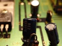
I will check the voltage and the heating of the chip a bit later and come back with updates. I appreciate that you like my high res photos :), so I put one with the C45 and C7 caps that have some white dust on them - maybe overheating from the chip?
*** LATER EDIT: voltage on the regulator is 10.7 V on input and 4.95 V output, the chips are cold besides the Zilog Z80 one - which is getting just slightly warm
|
| |
|
- Joined: 14 Mar 2013
- Posts: 62
- Location: Belgium
|
Posted: Mon Oct 01, 2018 2:40 pm
|
Those traces around C45 don't look too good.
You might want to check for continuity with a multimeter.
If you find a broken trace, then you can bridge it with a wire, like that black one on the bottom of the SMS2.
|
| |
|
- Joined: 14 Aug 2000
- Posts: 742
- Location: Adelaide, Australia
|
SMS 2 no cartridge loading
Posted: Mon Oct 01, 2018 4:09 pm
|
OK, the regulator looks OK and no chips are burning up. That's good.
It would be good to give the reset circuit a quick check. Can you measure the voltage on pin 26 of the Z80 CPU? After power up it should go to and stay at 5 volts.
|
| |
|
- Joined: 29 Sep 2018
- Posts: 6
|
Posted: Mon Oct 01, 2018 6:45 pm
|
asynchronous wrote OK, the regulator looks OK and no chips are burning up. That's good.
It would be good to give the reset circuit a quick check. Can you measure the voltage on pin 26 of the Z80 CPU? After power up it should go to and stay at 5 volts.
Thank you both for the tips!
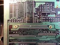
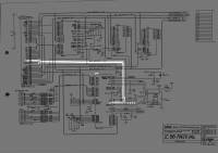
I've made a continuity check, and 3 out of 5 corroded wires are working. The other two I couldn't check because I'm losing the track of them, can't figure it out where they are heading. Nevertheless it seems that the corrosion is on the surface and is a high probability that this is not the cause. Is worth checking, but I'm stuck because the tracks on the scanned schematics combine at a certain point and don't know where they should go (please see the attached image - yellow and pink lines couldn't figure out the full path)
The pin 26 reads 4.95 V when it has a cartridge connected and is displaying only the SEGA screen only.
*LATER EDIT: I think I found the pin4 (IC4) connection to A7 (pin32 from the cartridge connectors) - it seems this is dead... now the question is, if this pin4 from IC4 is connected directly with pin 32? (except the resistor array). In the path that I draw - the yellow line seems is going under the SANYO chip).
|
| |
|
- Joined: 29 Sep 2018
- Posts: 6
|
Posted: Mon Oct 01, 2018 7:48 pm
|
Ok so I updated the photo and traces with problems so it will be more clear.
The pink line seems to have connection through the corrosion (don't know where it ends but could be functional if the corrosion didn't interrupt it).
The yellow line on the other hand, should connect to pin 32 (A7) from cartridge connector - as in schematics. This seems to fail to have continuity. Question is - is the corroded wire directly connected with the pin32 from CON ? I could first try to connect these points and check it out...
As per schematics seems safe to directly connect - let's say point where resistor array connects pin4 from IC4 and to Pin32 from CON? (please see attached image).
Thank you!
|
| |
|
- Joined: 14 Mar 2013
- Posts: 62
- Location: Belgium
|
Posted: Tue Oct 02, 2018 5:09 am
|
If you check the schematic A7 is part of the address bus which goes pretty much to all chips on the PCB.
You could check continuity of A7 on different chips and bridge where it's the easiest and shortest for you to solder onto.
Quote As per schematics seems safe to directly connect - let's say point where resistor array connects pin4 from IC4 and to Pin32 from CON? (please see attached image).
The resistor (from the resistor array) is there to ensure the A7 line stays "high" when unused.
You don't want something controlling addresses to just be "floating".
Make sure the connection between A7 and that pull-up resistor is fine too in case you didn't check that.
|
| |
|
- Joined: 14 Aug 2000
- Posts: 742
- Location: Adelaide, Australia
|
SMS 2 no cartridge loading
Posted: Tue Oct 02, 2018 5:49 am
|
You could also try reflowing the solder on the joints that A7 connects in the event the problem is a dry solder joint.
A7 connects IC1, IC2, IC3, IC4, IC5, the Cartridge slot and the above mention pull-up resistor.
Good luck
|
| |
|
- Joined: 29 Sep 2018
- Posts: 6
|
Posted: Tue Oct 02, 2018 7:38 am
|
asynchronous wrote You could also try reflowing the solder on the joints that A7 connects in the event the problem is a dry solder joint.
A7 connects IC1, IC2, IC3, IC4, IC5, the Cartridge slot and the above mention pull-up resistor.
Good luck
Guys I think I found it, I have connection on all IC1 to 5 and connector besides the IC4 (with pin4 + resistor). Basically I think I will have to wire the yellow line as I drew it but where is the question mark to be connected to pin3 of IC3. Having more experience than me, that makes sense also to you guys?
Thank you!
|
| |
|
- Joined: 29 Sep 2018
- Posts: 6
|
Posted: Tue Oct 02, 2018 8:01 am
|
Well, I took my chances and tried it.. and it works! it's alive!
Thank you guys for all the help!
|
| |
|
- Joined: 14 Aug 2000
- Posts: 742
- Location: Adelaide, Australia
|
SMS 2 no cartridge loading (SOLVED)
Posted: Tue Oct 02, 2018 10:44 am
|
|
Awesome! Good job.
|
| |
|
- Joined: 14 Mar 2013
- Posts: 62
- Location: Belgium
|
Posted: Thu Oct 04, 2018 6:52 am
|
Another one saved !
Good job.
|
| |
|