|
|
ForumsSega Master System / Mark III / Game GearSG-1000 / SC-3000 / SF-7000 / OMV |
Home - Forums - Games - Scans - Maps - Cheats - Credits Music - Videos - Development - Hacks - Translations - Homebrew |
View topic - Yeno SC3000 wrong color pallette
 |
| Author | Message |
|---|---|
|
Yeno SC3000 wrong color pallette
|
|
I've acquired this French Yeno SC3000 a few months ago and been working hard to trying to get it to work perfectly on my NTSC TV. I am using a Scart to HDMI converter, which works perfectly with my other systems with their own respective Scart cables.
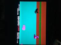
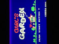
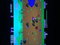
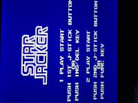
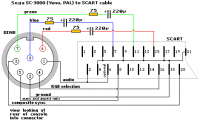
The system did not come with a Scart cable, so I ordered a SMS cable on ebay and modified it to follow this schematic I found online. Every resistor is the same and wired correctly. Since this system is a french Pal region running at 50hz, I switched the TMS9929ANL to a TMS9928AN to get it up to 60hz like a NTSC unit. Everything works great. Now the problem, is that the colors are wrong in some places. I only have two games, but the problem is mostly noticable in Girl's Garden. The ground is a brownish red instead of a more yellowish color, the whites have some red tint in some places, the reds and pinks are off...things are just all slightly off. In Star Jacker, sometimes the white lettering has a yellowish tint. I played with the three color pots on the internal rgb board, but the best image I can get is the one you see. Anything else is off or a mess. Both games don't look too bad, but knowing the colors are not as intended irritates me. I changed the capacitors to new ones on the internal rgb board, but no difference. I have no clue where to go next, does anyone have a clue on how to fix this? Many thanks in advance! 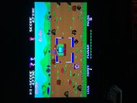
|
|
|
|
|
|
|
|
Taking a guess, two things come to mind.
Could be the secam video output messing up the colours. Could be that the proper sg1000 colour palette isn't available on the sc3000, but I'm not certain about this. |
|
|
|
|
|
|
| Could it be possible that I would need to put a TMS9918A instead? That's what's in the regular sg1000 and sc3000, maybe the color palettes are different? But I believe it's composite only (please correct me if I am wrong), so I'm wondering what would happen if the chips were changed.. | |
|
|
|
|
|
|
yes, TMS9918 is composite only.
TMS9929 is known to have a palette that differs from the TMS9918, so it may be that the TMS9928 has a different palette as well. How does the TMS9928 palette compare to the TMS9929 that was installed before? Just as a side note, I modded an sg1000 to get rgb (some models have a sega chip that provides rgb) and the colors were off as well http://www.smspower.org/forums/14640-WeirdPaletteWithRGBModdedSG1000II I wonder if they're off in the same way. |
|
|
|
|
|
|
| The first thing that comes to mind is the crystal oscillator, is it running the tms99x8 at the right speed for NTSC? | |
|
|
|
|
|
|
I haven't changed anything else except the TMS, and when I did change the TMS I changed it before I had completed my Scart cable (I was using another scart unmodified Master system cable to just test if the unit worked, colors were all out of whack and sound and gameplay was slower at 50hz) so I have no clue about the color palette. But I do know that only switching the chip made it run at 60hz, and the music and gameplay did get faster just like a NTSC unit. Maybe TMS9929 and TMS9928 share the same palette but at different speeds, and same would apply to both the TMS9918 and TMS9919? Can anyone confirm this? If it is indeed the problem, would going to TMS9918 be a possibility or would that only mess things up?
Looking at this; http://www.smspower.org/Development/Palette#MasterSystemMarkIII Almost seems like I got something resembling a lot the Mark 3 |
|
|
|
|
|
|
|
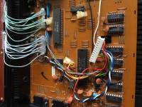
could you verify the markings on the crystal oscillator, the oval-ish square tin can with the grey plastic around it, top-left of the tms9928* chip? it should be around 10.738 mhz for ntsc. it uses a /3 divider to get 3579333mhz which is close to the ntsc colorburst clock (3579545)
Of course, without the correct crystal you are not going to get the correct colors... |
|
|
|
|
|
|
I just opened it up, and it seems to have the exact crystal you say it would need. I did notice this white jumper wire going across a dotted line printed on the board, saying PAL -3.58M System Clock. I tried unsoldering one end out to see if that did anything, but it only made a blank black screen. So I put it back. I am stumped with this, any more clues? 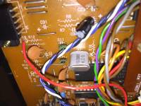
|
|
|
|
|
|
|
|
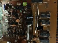
Ive not had much to do with the SC3000 so dont know too much about how the video hardware works. Ive got a PAL unit here but havnt paid too much attention to its internals. From what i understand the TMS992X video chip outputs a YPbPr video signal which is then converted to RGB, which is probably happening on that daughter board. Assuming it worked fine and had the correct colours before you swapped from a TMS9929 to a TMS9928 then one could assume that part was working ok.
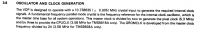
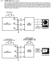
The data sheet for the TMS99XX has a little bit of info on this that may or may not be useful. Ive attached screen captures for reference. The note that is possibly worth looking at is about the oscillator (section 4.2.3). It mentions adjusting the capacitor values to help correct the colours. Could be worth looking at, as it looks like the crystal is correct. 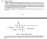
|
|
|
|
|
|
|
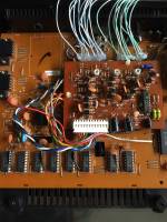
Are these sheets written for the SC3000? I checked 4.2.3, and the thing about the trimmer capacitor is very interesting. I found two C1 in my sega though, one on the main mother board and one on the video converter board. I assume they are talking about the mother board, but problem is that there is already a 4.7uf 50v in it's place. Meanwhile on the RGB board, c1 is empty of anything. |
|
|
|
|
|
|
|
Thoae were out of the datasheet for the tms99xx. If you google tms9918 datasheet you should be able to find a copy. It was too big to attach on here sorry.
On the sc3000 the circuit layout will be similar. Im going to guess those 2 green ceramic caps either side of the crystal are the caps youd want to be looking at. You will need to trace it out and double check tho. They will have used typical values that worked well in this application so you will want to change them for the values suggested in the datasheet to make it adjustable. |
|
|
|
|
|
Last edited by keiffer01 on Mon Mar 12, 2018 11:32 pm; edited 1 time in total |
I'm about to give up. I installed a trimmer capacitor of 5.5-65pf on one of the green caps. Nothing changed even when adjusting. I even switched it on the other green cap. Still nothing. I put the green caps back, unsoldered the TMS9928 and installed a 40 pin socket so I could then easily test the TMS9929 and revert back to the 9928. Colors are all the same, but the image is slightly squished from top and bottom and obviously the games are much slower. I tried adjusting the color pots again, nothing different. I put the TMS9928 back in the socket, adjusted again and called it a day. I think it all comes down to a different color palette than the TMS9918. If you have a Yeno RGB SC3000, you will have a really nice crisp image but colors are all slightly off. It honestly doesn't look bad at all, it looks great. But knowing it's not as intended...sigh. Wish there was an easy way to correct this... |
|
|
|
|
|
|
| The datasheet didnt mention anything about them having different colour pallets. The difference between a tms991x and a tms992x seemed to only be the video output. One was composite video and the other was YPbPr. | |
|
|
|
|
|
|
I know this is a little random, but the colors look comparable to the palette when playing sg1000/3000 games on the Master System and Mark 3 which I find odd. Take a look at the Dark Yellow, the color I should be getting for the ground in Girl's Garden. It's the same as I get. ;
http://www.smspower.org/Development/Palette#MasterSystemMarkIII I don't want to give up on it, but damn I can't find the solution. As it sits now, this is beyond my knowledge. If I get the same results from the TMS9929 like originally installed, and that the TMS992X really do share the same palette as the TMS991X, and lastly the oscillator crystal is good already for NTSC at 10.738mhz... the problem is maybe within the RGB encoder board? |
|
|
|
|
|
|
Maybe it's a late model that uses the same VDP as the SMS, for some reason? In any case, are you guys 100% sure that this is not a case of this hardware revision having a different palette by design, just like the PAL Atari 2600? |
|
|
|
|