|
|
ForumsSega Master System / Mark III / Game GearSG-1000 / SC-3000 / SF-7000 / OMV |
Home - Forums - Games - Scans - Maps - Cheats - Credits Music - Videos - Development - Hacks - Translations - Homebrew |
View topic - Adding Light Phaser + 3D support to Game Gear
 |
| Author | Message |
|---|---|
|
Adding Light Phaser + 3D support to Game Gear
|
|
Hey folks,
In my never ending quest to turn my Sega Game Gear into an ultimate mini SMS, I have been brainstorming and reverse engineering ways to make all the games compatible. I have already uncovered a mod for both Japanese and PAL modes (to play Pop Breaker and a lot of the SMS PAL library) and now I want to tackle the missing hardware support. The idea is this: taking a broken SMS1 and adding the necessary 315-5204 Gate Array chip into the Game Gear. All the signals are there in the (2 ASIC) VA0 model. Interestingly enough, almost everything for an SMS1 is in there. There is external RAM, Z80, even the original VDP shrunk down to SMD form. Sega just consolidated the Gate Array into a single ASIC that also drives the LCD panel, handles Gear to Gear Cable I/O, TV tuner support, and has the audio DAC (instead of it being with the VDP). My question is this: if I do this mod there will be two Gate Arrays that the CPU will be seeing, hooked up parallel so-to-speak. Because I cannot undo the internal one in the Sega ASIC. Would this confuse the data lines at all? I feel like it could work....but it is a crazy idea :) For reference, I'm talking of IC4 in this pic: http://www.smspower.org/uploads/Development/SegaMasterSystemServiceManual-schema... |
|
|
|
|
|
|
|
Um... I am not convinced that this will work.
The GG screen has less resolution. That's 144 scan lines compared to 192 for the SMS. If the SMS chip requires exactly 192 scan lines, then it won't work in the GG hardware. Assuming the SMS to GG hardware transplant is successful ,which is unlikely: 1) How do you plug a light phaser into the game gear? Button 1 of the control pad must be replaced with the light phaser trigger. It can not be separate I/O. 2) The light phaser probably will not work on a tiny screen. To work the light phaser, you turn the screen white scan line by scan line. The light phaser sees a circle of the screen. Size of the circle is dependent upon how far away you are from the screen. Once it sees white, the program can read which scan line (Y coordinate) and how far the scan line was (X coordinate - this is where special hardware comes in). But this X,Y is on the outside of the circle. The program then does some math to guess where the center of the circle is. 2a) If you shrink the screen size drastically, the math done by the program will probably give you the wrong center. 2b) If you shrink the screen size drastically, even putting the light phaser right next to the screen will give you too big a circle of vision. Please try reading the software reference manual for the sega mark iii console. It explains how the light phaser works and may answer some more of your questions. |
|
|
|
|
|
|
|
Thanks for the reply. I think you misunderstand what I am intending here. I should have been more clear in my first post.
This is to be used with a modded Game Gear with TV output in SMS mode in order to play games like Rescue Mission. The Game Gear modded for TV output in SMS mode is full-screen 60hz and as far as I know, has all the same specs of a full SMS. This concept does not apply to the game gear screen or "windowed" games. The light phaser uses pin 7 on the control pad. I would add a controller port to the Game Gear of course (I've done this before, it is easy to do). Pin 7 (Th) is not present in the Game Gear because Sega left it out since obviously they didn't plan on light gun support. The 315-5124 (also sometime labelled 315-5204) produces "Th", the I/O signal for the light phaser pin on the controller port. By adding the Gate Array IC (315-5124) in parallel with the other bus data lines, the CPU would see 2 Gate Array ICs, but I think the logic might be low-level enough that this would not create a conflict. Edit: SMS2 also has a gatearray IC: http://gamesx.com/wiki/lib/exe/fetch.php?media=schematics:sms2_schematic_-_ic_bd... and the GG VDP in has quite a few mystery "NC" pins worth looking into... -Segasonicfan |
|
|
|
|
|
|
|
Oh, sorry. I thought you were using the GG screen. If the hardware transplant works and the output is on a TV, then everything should be OK.
I'm more of a programmer than a circuit designer, so I wouldn't know details about the chips. |
|
|
|
|
|
|
|
Looking into it more, a hardware transplant just won't work. There are signals missing and honestly it's a very risky job. Plus, I can't find a broken system for cheap right now.
However, I am 90% sure now that EXT port of the GG has the necessary "TH" line for the light phaser. It is labelled PC6 in this schematic: http://gamesx.com/wiki/lib/exe/fetch.php?media=schematics:game_gear_va0_schemati... And is the same signal used in the Genesis (labelled PA and PB here): http://gamesx.com/wiki/lib/exe/fetch.php?media=schematics:genesis_cpu_and_custom... However, this is only supported for 2Player in the Game Gear. Meaning, there would have to be a way to configure the GG to see the 2player TH input as a 1P TH input, if this is possible. Because most lightgun games are 1P only unfortunately. Here's where things get interesting though. Using my Safari Hunt/Hang On cart on my model 1 SMS it requires you to "aim a lightgun at the screen and press button 1" to start Safari Hunt. If I aim PLAYER 2s gun at the screen and press Player ONE start then then the game boots! But only if I aim the gun, which means it IS registering the light phaser. However, I have yet to get it to register in-game using this method. Any ideas ? It would be so neat to use a light phaser on GG... |
|
|
|
|
|
|
|
If my memory serves right, at Safari Hunt & Hang On selection screen, Safari Hunt will only run, when the player press button 1, if the VDP HCounter is latched with a value. I didn't verify if the value needs to be in a range or just needs to be greater than 0. TH input isn't checked when that screen is displayed. The HCounter latch is done when a Light Phaser aims at the screen, doesn't matter if it is connected to controller 1 or 2 port, as you discovered. I don't know if there's a Light Phaser game that doesn't poll TH line, I guess all of them requires it.
I took a look at images of the Game Gear official document and the maintenance PDF manual of VA0 we have. In gg-officialdocs-png.zip, file main-6.png contains an image of port $DD bit functions that includes TH bit of the EXT port. It lacks TH bit for player 1, that could be just undocumented, however, I didn't find the relative TH pin in the pinouts of the 315-5378B chip described at page 67 of the GameGearMaintenanceManualEuropeVA0.pdf file. Player 1 inputs are pins 7-13: UP, DW, LE, RI, TL, TR, PS. I guess you don't have an option with the original GG chips that doesn't require hack the Light Phaser games to use player 2 instead player 1 input, else you will just be able to shoot in the name for player 2 in Gangster Town. I you find another Game Gear to do hardware tests, please also try some of those NC pins of the GG VDP to see if there's one that disables the bigger borders of the GG native mode. |
|
|
|
|
|
|
|
Thanks for the reply enik!!
Yep, you seem to have noticed what I did - the Player 1 has no TH pin coming from the CPU ASIC. Perhaps there would be a way to hack the game rom to support player 2 light gun as player 1? I don't know how hard that would be (I don't know software at all sadly). Strange that sega would make the option possible for player 2 but leave it out for player one. Not that GG was meant to hook up to a TV anyway :p I noticed those NC pins on the VDP as well. They are only present in the VA0 Game Gear and could be very interesting. I do in fact have a spare one to poke around in. What do you think would be the best way to test it without a logic analyzer? I could latch stuff to logic high/low with a 10k resistor and see what happens, though that is a little risky. Honestly I was hoping some of those pins would be analog RGB outs like the SMS VDP has (they are very similar) but they don't appear to be analog voltages at all and testing showed nothing on a monitor. I am very curious though! |
|
|
|
|
|
|
| Sorry, I don't have enough knowledge in electronic circuits to help. I suggested just in case you really get a cheap, broken system, not to try on your modded GG. I never hacked a ROM file, so I can't help either, but other people in this forum have made more complex hacks, like the ports of GG games to play on the SMS. | |
|
|
|
|
|
|
You intercept the data line going to the CPU.
ASIC will also respond during the access and you cannot just wire something in parallel to it that also wants to respond, you'll create a bus fight like that. Small CPLD will do the trick, much better than a handful of logic chips doing the stuff. |
|
|
|
|
|
|
Ah, I wish I had the skill to make such a complex hack. Not enough love out there for the GG either, I don't expect anyone to do this. It would be great though! The GG could then play everything but 3D games! It is even fully PAL capable. It's got everything except lightgun + 3D.. |
|
|
|
|
|
|
| 3d should work and would be easy to do but you would need tv out and a crt based tv. Have you got a 3d adapter to use? At minimum you need to connect A15, A13, A2, D0, Write, +5v and Gnd. Some other pins on the 3d adapter then needed to be connected to ground and +5v, but i can make up a table with that info on it if you need. | |
|
|
|
|
|
That would be AMAZING, could you please make a table? Thank you! I have a 3D adapter to use. -Segasonicfan |
|
|
|
|
|
|
|
See how this looks... I counted the pin numbers from the pin out diagrams in the development sections so there could be errors in my counting. Double check against the pin names if you like, with the exceptions of CE and MemReq. CE on the 3d adapter needs to go to +5 and MemReq is not present on the GG cart socket so can be connected to ground. Ive included a complete wiring table and a simplified table. The simplified one has 10 less wires between the 3d adapter and the GG.
Let us know how you get on |
|
|
|
|
|
|
|
Thanks for this awesome info. I'm gonna try this after I desolder a connector for it from an SMS.
Question: how do you know the 3D glasses only use these data lines? I'm particularly concerned about the lack of the CONT signal on pin 34. This comes from the gate array IC and seems rather important: http://gamesx.com/wiki/lib/exe/fetch.php?media=schematics:sms_schematic_-_ic_boa... I don't know enough about code to know how the glasses work and with what signals though. This page has some interesting info on someone trying to hack the 3D glasses into a genesis: http://www.smspower.org/forums/13935-IntegrateSega3DAdapterIntoGenesis apparently there are a couple pins missing from your list and one of them is CONT which seems like it might be necessary. I'm wondering if thats what is handled by the power base converter chip here: http://www.the-liberator.net/site-files/retro-games/hardware/SEGA-Mega-Drive-Mas... I just want to be careful I don't embark on a huge project that technically isn't possible with just wiring to the address lines and such. -Segasonicfan |
|
|
|
|
|
|
|
The way the 3d adaptor works is fairly simple. It uses data bit 0 at address $fff8 to control which eye on the lcd glasses is dark and light. The game writes to the memory location and the adapter detects the write on the bus, but is never actually involved with any communication.
Theres a circuit diagram of it here.. http://www.smspower.org/forums/14635-SegaCardFor3DGlassesCircuit#78110 Ive built a couple of prototypes based around the circuit above and had a bit of trouble getting it going, like the person with the genesis was having. In the end it was to do with the CE line. More info here.. http://www.smspower.org/forums/15125-MemoryAddressToBusPinStates3dGlassesInterface#83033 Ive since made a drop in 3d module for the sms2 that uses the same simplified pinout, which ive also tested on the megadrive/genesis. http://www.smspower.org/forums/15248-Sms2Mods Seems a bit of a shame to take the card slot out of a master system 1 for this though! |
|
|
|
|
|
|
|
Wow, that is some really cool work you did there (!) I'm really stunned. Any chance you could sell me one of the 3D glasses PCBs you made so I wouldn't have to take the connector out of an SMS? I think it is pretty much impossible to find otherwise. Plus, I really could use a smaller board so I can squeeze it inside the GG! I've already done a definitive LED backlight hack that I'm going to post a guide on soon and some other nifty stuff - trying to make this the most awesome GG on the planet :)
-Segasonicfan |
|
|
|
|
|
|
| Ive only got 2 built at the moment but will build more to sell. I had some one else ask me the same thing, lol. I actually wondered about doing another spin of the board and making it smaller so it fits nicely inside a game gear and or megadrive/genesis. The one i did for the sms2 was just to fit the gap between the fm interface pcb i did and the mounting posts that were already part of the case, so it wasn't the best use of board space. How much room is there in a game gear once you put a tv out board in? If we can find a good spot for it ill see about making something to fit. Actually, are you able to tell me the dimensions of the tv out board? Thats probably all i need to know. | |
|
|
|
|
|
|
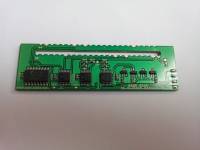
Just measured Viletim's board: it's approx 73mm x 31mm. My personally made PCB is a good bit smaller but it takes a lot of extra work to build.
also, if you do the DSi LED backlight mod you have a ton of extra room in there. I was able to put the TV out board behind the LCD even with lost of room there to spare! see my attached pic. How much would you charge for one of these boards? They seem to be very good build quality. -Segasonicfan 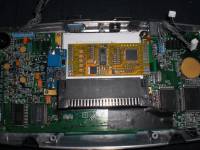
|
|
|
|
|
|
|
|
Thanks for that, thats a good starting point. Ive got 3 or 4 game gears at home (probably still in bits) with crook lcds so ill dig one out and have a look it.
I started this ago, and got the bits progressively, just never quite got around to finishing it off until the other week. I havn't even looked at what one actually cost to build... i would imagine it was less than $20 nzd though. A game gear varient should be simpler as its got an internal 34v supply we can use, so i can probably get rid of the power supply i used and several caps to go with it and just use a regulator instead. |
|
|
|
|
|
|
|
I'm confused, I thought it all just ran off +5v? The +34v inside the GG can't take hardly any load on it. I tried to step it down and power the backlight off it but it wouldn't go at all without an inductor replacement on the DC-DC side of things. It's super-low current output. Pretty much any power from the GG has to be used (stepped up or down) from the +5v line.
$20 really isn't bad! hopefully you aren't too hungry for the profit :) Though of course you deserve something for all your hard work. -Segasonicfan |
|
|
|
|
|
|
|
A higher voltage is needed to drive the LCD glasses properly. On the real 3d adapter its got a charge pump arrangement that produces 10v or so from the 5v supply to the card slot. It works but it doesn't drive the 3d glasses well enough to completely block out light. I used a small power supply to get ~20v on mine, which drives them better. The actual current consumption is only a few mA and given theres a 34V connection of the cart socket (i think the tv tuner used it) its probably safe to assume theres useful current available.
Looking inside this game gear ive got here theres annoyingly not much room with a stock back light and the spot for a tv board taken away. Wonder if i can make something sweet that fits on the front side of the board instead. Do we care where the socket for the glasses goes? |
|
|
|
|
|
|
| Ok, not sure if any one else is likely to want a 3d adapter for the game gear but ive had a look and have found a sweet spot thatll work well. Ill machine something tomorrow at work and check the fitment but im guessing itll be fine. | |
|
|
|
|
|
So Interesting!! So it makes the glasses look even better than stock, huh? another easy alternative is just using +5v with this: http://www.ebay.com/itm/2A-booster-board-DC-DC-step-up-module-input-2-24V-to-5-2... But you are probably right (if consumption is that low). Should work fine.
Heheh, I'm used to SO much less room in my projects, the inside of the GG feels like palace to me with all its roominess (Sega designed the case with a ton of extra space compared to say, a Nomad or CDX). I think the socket for the glasses isn't so important since the cable they use is SO long. But if it's possible it is always nice having the socket face you- so sticking out from the bottom would be nice. But wherever you can fit it works. You can also mount the board elsewhere and use a threaded panel mount audio jack. Note: there is actually space above the video converter board. The clearance is pretty high with that space inside the GG. All you have to worry about is the threaded screw hole for the Master Gear Converter.
Well you have at least one devoted fan here :P Looking forward to what you come up with !! Where do you work that you can make such great PCBs, btw? -Segasonicfan |
|
|
|
|
|
|
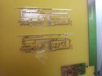
A circuit board manufacturing company, lol. Here we go.. i ran off a mechanical mock up tonight. Fits sweet, clears everything it needs to and itll solder straight in like my FM adapter board does. The only wiring involved will be the 3.5mm socket. Now i know itll fit i can work on the board layout, but probably wont get time for that till next week. Itll be pro when its done anyway. 
|
|
|
|
|
|
|
|
Awesome! That's a nifty little spot to fit it too.
The only downside I can see is it won't work on a VA5 Game Gear (produced in 1994). These are uncommon and with 7 or 8 revisions I don't think it's a very big deal. The reason why is the different screen: http://i18.photobucket.com/albums/b134/Segasonicfan/GGTV/GG%20VA4%201995/CIMG287... 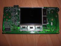
|
|
|
|
|
|
|
| Wow look at that lcd.. definately wont fit on that one. Is that an odd ball unit that sega made or is it the majestico model? Ive not really had much to do with game gear hardware... | |
|
|
|
|
|
|
It's an official Sega one. I've opened up dozens of Game Gears over the years and this is a pretty uncommon one. Only the VA8 is Majesco (I think). This is 1994, so a good 4 years before the Majesco ones were made in 1998.
Your mod idea is great though, it will work on probably 95% of GGs out there. |
|
|
|
|
|
|
| Managed to spend a few mins working on the board layout last night. If im lucky i might have a proto revision assembled ready to test later this week. I had a thought this morning though.. is the tv out always ntsc/60hz from a game gear? Its not switchable? Ive only tested my 3d board on pal/50hz systems. It probably wont matter but there could be some timing issues. I might have to wire in a 50/60hz switch on my test sms2 and see what happens. | |
|
|
|
|
|
| Right, 3D at 50Hz is sorta crap.. 60Hz on the other hand, soooo much better. The timing issues i wondered about seem fine too, but i guess thats right as there isn't a PAL and NTSC version of the 3d adapter, which there would be if there were issues. | |
|
|
|
|
|
I found a way to switch the GG into PAL mode last year, thanks to the dumped schematics: http://www.smspower.org/forums/14665-GameGearNowInPAL50hzModeButNeedHelpForTVOut Pin 119 to +5v on a 1 ASIC will put it into 50hz PAL for a 2 ASIC, pin 25 on the VDP needs to be +5v and also pin 19 on the ASIC CPU. -Segasonicfan |
|
|
|
|
|
|
I spotted my board coming out of the etch this afternoon. Should be able to throw it together on the weekend and get the scope out and see what happens. Still missing some transistors that havn't turned up yet but probably don't really need them. Ive brought a GGTV board too, so ill have to put that in i guess, although if it looks fine on the scope it should work.
|
|
|
|
|
|
|
|
Looks great! I'm excited to see the final product. My GG is wired in like frakenstein so if I get one of these I'm gonna try to wire the 7 points on the back of the PCB since I don't want to take out my LCD and rewire everything again :P
-Segasonicfan |
|
|
|
|
|
|
| Ive used a couple of extra pins on this one, so 9 in total now? The extra ones are the 34v supply and the GG pin. I thought id be cleaver and use the GG pin to switch it off when its not in SMS mode to save battery. That can be wired out if needed though. | |
|
|
|
|
|
That is pretty clever! However, wont that mean its draining power when playing normal SMS games? the GGTV board by Viletim has an active low enable pin. You could use this (only active when a video cable is plugged in, like I did on mine) or use a headphone pin with an internal switch (the kind with 5 pins, used for switching audio when you plug in a jack). |
|
|
|
|
|
|
|
Put my 3d board together this morning and got that in. Had a small error on the board but managed to mod that and get it going. Still waiting on a couple of transistors to arrive so couldn't check that it turns off in game gear mode, but i don't see why it wont work. Can probably tidy the board layout up and get some real ones under way now :) Works fine on TV out too.
On another note.. i was checking it with Zaxxon 3D. This particular game gear doesnt have the blue "produced by or under license from sega enterprises ltd" bios boot screen. I noticed that the game came up with a Mark III screen though... is it likely to be a Japanese region game gear? 
|
|
|
|
|
|
|
Wow- that looks *amazing!* you make some really great board designs :) The BIOS screen only shows up on certain GGs. Earlier models (the VA0 for sure) don't have it. Yours doesn't look like a VA0 though so I don't know for sure. Try out a GG game and you'll know. The Mark III showing up IS cool though - maybe it is JP! You can tell from the back because the sticker for the model and such looks different. |
|
|
|
|
|
|
|
any more updates ? I'm eager to hear your progress wasup :)
-Segasonicfan |
|
|
|
|
|
|
|
I did another revision last week but that was a giant fail on my part, and didn't really fix my problem. Got another one under way now which will hopefully have it sorted. Just need to wait on a couple more parts to arrive and ill test it out.
Ive added an enable pin to it, which can be connected to the enable pin on the GGTV board. That will turn the glasses on/off. I was going to use the GG pin to switch the glasses on/off as well but that became too complicated without increasing the part count so ive just used that to disable the addressing until in SMS mode, which might save a small amount of power usage. It also stops the glasses going mental when loading a game on an everdrive, which is nice! I might look at learning how to use CPLDs at some stage as a small one would make this a bit nicer, although that will have to be later on down the the track. Need to get this one sorted first and worry about doing rev2 later :) |
|
|
|
|
|
|
| awesome! thanks for the update. I'm glad you decided to use the GG enable pin on Viletim's board. I think it is a nice way to go. | |
|
|
|
|
|
Put the latest board together tonight. It needs a small mod but it seems to work as expected. Enable/Disable works now. It was getting a bit messy to check anything else but its looking positive. Need to add some sockets to this unit rather than having wires just floating all over the place, lol. Might look at that tomorrow.
|
|
|
|
|
|
|
|
Looks so awesome!!
now the last* hack left for Game Gear....... FM support! lols ;P |
|
|
|
|
|
|
|
wasup: are you still going to mass-produce these boards? They are really great, I think you should :)
-Segasonicfan |
|
|
|
|