|
|
DevelopmentSega Master System / Mark III / Game Gear |
Home - Forums - Games - Scans - Maps - Cheats - Credits |
Documents
Documents in bold are those generally known as most up to date or accurate.
Note that wiki pages are generally more complete/accurate.
General System Documentation
| Document | Author | Description |
|---|---|---|
| SMS/GG hardware notes (2002/11/12) | Charles MacDonald | General and very complete documentation about the SMS/GG. See also "SMS VDP Documentation" by the same author. |
| Sega SC-3000 Hardware Notes (2004/07/29) | Charles MacDonald | Very complete notes on SC-3000 and related systems |
| Sega System E Hardware Notes (2010/05/27) | Charles MacDonald | Notes on the Sega System E arcade board |
| Sega Master System Technical Information | Richard Talbot-Watkins | General and very complete documentation about the SMS |
| Official SMS/GG documentation | Sega | The real thing. Note that it's less detailed and accurate that some newer documentation. It is still an interesting read. |
| Sega Master System and Game Gear Architecture (1.0) | Marat Fayzullin | (OUTDATED) Incomplete but covers quite a few interesting things |
| Jon's Technical Documentation (1991/11/23) | Jon | (OUTDATED) Very old document covering many aspects of the SMS/GG |
| Super Majik Spiral Crew's Guide to the Sega Master System (0.02) | Super Majik Spiral Crew | (OUTDATED) General documentation about the SMS |
| Game Gear Documentation | Unknown | (OUTDATED) Covers video ports, video registers, and inputs ports |
| Full port 3F and controller port details | Asynchronous | (OUTDATED) Forum post regarding SMS port $3F |
| Mail Extract #1 | James McKay and Neon Spiral Injector | (OUTDATED) Miscellaneous issues |
| Sega Game 1000 (SG-1000) Information (Draft) | Omar Cornut | (OUTDATED) Stripped down SMS documentation covering only SG-1000 specifics |
| techdoc.txt | PolestaR (Jason Starr) | (OUTDATED) Notes on CodeMasters games, Light Phaser, Paddle, 3-D Glasses |
| Sega Master System Schematics | Gringoz | Sega Master System Schematics |
Z80 Processor
| Document | Author | Description |
|---|---|---|
| Z80 Family CPU User Manual | Zilog | Official Z80 User's Manual (Zipped PDF document) |
| The Undocumented Z80 Documented (0.91) | Sean Young | Excellent document covering some of the less known Z80 aspects |
| Zilog Z80 Product Specification | Zilog | Official Z80 documentation |
| Zilog Z80 Documents | Various | Miscellaneous collection of Z80 documents documents |
Video
| Document | Author | Description |
|---|---|---|
| SMS VDP Documentation (2002/11/12) | Charles MacDonald | Excellent document covering the SMS and GG VDP hardware. See also "SMS/GG hardware notes" by the same author. |
| TMS9918A Data Sheet | Texas Instruments | Official specification of the TMS9918a Video Display Processor (VDP) (used by SG-1000/SC-3000, and in legacy video modes on the Master System) |
| TMS9918 Arizona Technical Symposium Draft | Karl Guttag, Texas Instruments | Semi-official discussion of the TMS9918a design and operation |
| Portar (1.5) | Mayer | Very complete MSX documentation (MSX uses a TMS9918 video chip) |
| TMS9918A Document | Sean Young | Description of the Texas Instruments TMS9918a Video Display Processor(VDP) |
| Super Majik Spiral Crew's Guide to using their code (0.00) | Super Majik Spiral Crew | (OUTDATED) Primitive documentation regarding the tile format and the palette |
| Sony CXA1145 Data Sheet | Sony | Official specification of the Sony CXA1145 Video Encoder (used in many Master System consoles) |
| Sony V7040 Data Sheet | Sony | Official specification of the Sony V7040 Video Encoder (used in early Master System consoles) |
| Fujitsu MB3514 Data Sheet | Fujitsu | Official specification of the Fujitsu MB3514 Video Encoder (used in some Master System consoles) |
| ROHM BA7230LS Data Sheet | ROHM | Official specification of the ROHM BA7230LS Video Encoder (used in the Mark III) |
| Motorola MC1377 Data Sheet | Motorola | Official specification of the Motorola MC1377 Video Encoder (used in early Brazilian Master System consoles) |
Memory System
| Document | Author | Description |
|---|---|---|
| Sega 315-5208, 315-5235, and 315-5365 Master System Memory Paging Chips | S8-Dev Team | Description of 315-5208, 315-5235, and 315-5365 paging chips and their use in homemade development cartridges. |
| SMSArch Documentation | Eric Quinn | Covers memory map and paging registers |
| Mail Extract #2 | James McKay | (OUTDATED) Covers paging registers |
| 93c46doc.zip | Microchip | 93C46B serial EEPROM document (used on some GG games) |
| NEC D4168 Data Sheet | NEC | Official specification of the NEC D4168 8KB XRAM (used for RAM and/or VRAM in many Master System consoles) |
| Samsung KM6264B Data Sheet | Samsung | Official specification of the Samsung KM6264B 8KB SRAM (used for RAM in some Master System consoles) |
| Sanyo LC3664B Data Sheet | Sanyo | Official specification of the Sanyo LC3664B 8KB SRAM (used for RAM in some Master System consoles) |
| Hitachi HM65256B Data Sheet | Hitachi | Official specification of the Hitachi HM65256B 32KB PSRAM (used for VRAM in some Master System consoles) |
| Sony CXK3864 Data Sheet | Sony | Official specification of the Sony CXK3864 8KB ROM (used for the BIOS in some Master System consoles) |
Sound
| Document | Author | Description |
|---|---|---|
| SN79489 notes | Maxim | Excellent document covering the SN79489/SN76496 |
| YM2413 Application Manual (HTML) | Yamaha / Maxim | Programmer's manual for the YM2413 sound generator, converted to HTML and with redrawn diagrams |
| YM2413 Application Manual (PDF scans) | Yamaha / Ricardo Bittencourt / HansO | Programmer's manual for the YM2413 sound generator, converted to PDF |
| YM2413 Application Manual (Scans) | Yamaha | Programmer's manual for the YM2413 sound generator |
| YM2413 Programmer's Manual (PDF) | Yamaha | Programmer's manual for the YM2413 sound generator |
| Project SMS OPLL | Leonard Silva de Oliveira | Schematics and mail extract about Leonard's successful attempt to adding a YM2413 for his non-Japanese Master System. |
Tapes/disks
| Document | Author | Description |
|---|---|---|
| SC-3000 Tape Format Notes | Sega | Four scanned pages from manual with notes about SC-3000 tape format. |
| NEC μPD765A Floppy Disk Controller manual | NEC | Manual for the FDC used in the SF-7000. |
Pinouts
| Document | Author | Description |
|---|---|---|
| Game Gear Pinouts | Unknown | Standard GG cartridge pinouts |
| European - Japanese Master System connector & MasterSystem - GameGear converter | Sankichi | Export/Japanese SMS pinouts, GG pinouts |
| SG-1000/SC-3000 pinouts | Skyhigh | SG-1000/SC-3000 pinouts and mail extracts |
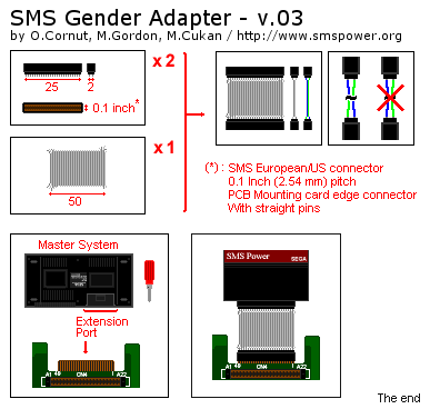
| SMS Gender Adapter Instructions (v.03) | Mike Gordon / Omar Cornut / Mike Cukan | Picture showing how to build a simple gender adapter to plug a cartridge on the expansion port. It is especially useful to play export games on a Japanese Master System. |
| SMSArch Documentation | Eric Quinn | Include SMS pinouts |
Development Tools
| Document | Author | Description |
|---|---|---|
| SMS 512K Flash Memory Cartridge | Charles MacDonald | Instructions to modify a SMS cartridge to accept a Am29F040 flash memory chip |
| 128k EPROM modification for 315-5208 based SMS cartridges | Mike G. | Procedure for creating a 1 Megabit re-programmable development cartridge. |
| Homemade Devcarts, Chapter 1 | Flavio Morsoletto | Introduction to creating homemade SMS development cartridges |
Miscellaneous
| Document | Author | Description |
|---|---|---|
| JavaGear Final Project Report | Chris White | Final project report submitted by Chris White to his computer science school. Covers the development of the JavaGear emulator. |
| JavaGear Specification | Chris White | Original project specification of the JavaGear emulator. |
| Game Gear Sound Fix Instructions | Ky Crout | Instructions to fix the sound problem happening on many Sega Game Gears. |
| S8-Dev Standards Committee (SDSC) | Eric Quinn & SMS Power! | An attempt at creating standards for Sega 8-Bit console software development. More or less aborted in 2001. |
Also check variety of technical tests and tools running on native hardware in the Homebrew section.
Books
| Document | Author | Year | Description |
|---|---|---|---|
| Programming the Z80, 3rd Ed | Rodnay Zaks | 1980 | |
| The Art of Computer Game Design | Chris Crawford | 1982 | |
| The Z-80 Microcomputer Handbook | William Barden, Jr. | 1985 | |
| Z80 Assembly Language Subroutines | Lance A. Leventhal & Winthrop Saville | 1983 |
