|
|
DevelopmentSega Master System / Mark III / Game Gear |
Home - Forums - Games - Scans - Maps - Cheats - Credits |
Sega Master System II Service Manual
This page is based on OCR of original Sega documents. There may well be errors in some parts!
Also available in:
 |
Discuss thisThere is a forum topic for Sega Master System II Service Manual |
Sega Master System II Service Manual
April 1991 Sega Enterprises, Ltd. Overseas Consumer Products Division
- General
- Repair Procedures
- Diagrams and Parts Lists
General
1. PRODUCT NUMBER AND COLOR SPECIFICATIONS
| Territory | Model No. | Color Format | System | RF Modulator | Channel |
|---|---|---|---|---|---|
| America | MK-3006 | NTSC | M | 200-5118-01 or 200-5115 | 3/4 |
| Canada | MK-3006-22 | PAL | B (VV) | 200-5194-02 | 3/4 |
| Australia | MK-3006-03 | PAL | B(VE) | 200-5198 | 0/1 |
| N. Zealand | MK-3006 | PAL | D | 200-5139 | 2/3 |
| China | MK-3006-15 | PAL | G | 200-5086-02 | 3/4 |
| Germany | MK-3006-18 | PAL | G | 200-5086-02 | 36 |
| France | MK-3006-09 | PAL | RGB | NONE | - |
2. AC ADAPTOR SPECIFICATIONS
| Territory | Parts Model No. | Number | Diagram Number | Voltage/Frequency | Plug Type |
|---|---|---|---|---|---|
| America | MK-3006 | 400-5115 | H-0246 | AC 120 V + 10%/ 60Hz | A Type |
| Canada | MK-3006-22 | 400-5123 | H-0249 | AC 120 V + 10%/ 60Hz | A Type |
| Australia | MK-3006-03 | 400-5050 | H0133 | AC240V + 10%/ 50Hz | S Type |
| N. Zealand | MK-3006-04 | 400-5050 | H-0133 | AC240V + 10%/ 50Hz | S Type |
| China | MK-3006-15 | 400-5093-91 | H-0158-01 | AC220V + 10%/ 50Hz | A Type |
| Germany | MK-3006-18 | 400-5126 | AC220V + 10%/ 50Hz | C Type |
3. PRODUCT DIMENSIONS AND WEIGHT
- Main Unit Dimensions
- 256 (W) x 172 (D) x 81.5 (H) mm
- Main Unit Weight
- 790 g
- Packed Dimensions
- 360 (W) x 216 (W) x 125 (H) mm
- Packed Weight
- 1.7 kg.
- Master Carton Dimensions
- (6 pcs./carton) 450 (W) x 400 (D) x (390 (H) mm
- Master Carton Weight
- 11.5 kg. (0.072 m3)
4. ELECTRICAL SPECIFICATIONS
- Power
- AC 220V or 240V, 50Hz
- CPU
- Z-80A 3.58 MHz
- RAM
- 64 Kbit
- V-RAM
- 128 Kbit
- ROM
- 1Mbit
- Scrolling Screen
- 256 x 192 dot
32 colors displayed from a palette of 64 - Sprite Screen
- 64 sprites of 8 x8 dot or 8 x 16 dot on screen
16 colors displayed from a palette of 64 - Character Patterns
- Maximum of 448 types
- Scrolling Directions
- Horizontal, Vertical, Diagonal
- Sound
- Three types plus noise
Repair Procedures
1. Flowchart For Troubleshooting Fault Locations
Power switch check
 |
 v
IC8 OUT +5V check
 |<------- Reset circuit check
 v
XTAL 10.738 MHz output clock <-- IC4; pin41
 |
 v
IC1: pin6 clock 2.58 MHz check
 |
 v
IC2: pins 20, 22, pulse IN check
 |
 v
IC3: pins 1, 20, 22, 27 pulse check
 |
 v
IC5: RGB signal. C. SYNC signal check; Audio signal check
 |
 v
IC6, IC7: pins 20, 22, 27 pulse check
 |
 v
IC9: pins 1 to 2, 3, 4, RGB IN check; pin 19 to 20, C. VIDEO OUT check
 |
 v
RF modulator IN check; RF modulator OUR (+ 5 V) check
2. MAIN UNIT (POWER BASE)
(A). Servicing the Main Unit (Power Base)
NS=10-9s
|
Parts Test Procedure |
Fault Location |
Symptoms |
|---|---|---|
|
1. IC 8 (LM7805) power chcck.
|
|
|
|
2. Power check of ICs
|
|
|
|
3. Is reset circuit operating?
|
|
|
|
4. Is oscillator circuit working?
|
|
|
|
5. Check conncctors
|
|
|
|
6. Check button switches. | ||
|
|
|
|
|
|
|
7. Check RF modulator | ||
|
|
|
|
|
|
(B) Possible symptoms for each fault location
| Fault Location (Contents of malfunction) | Symptom |
|---|---|
| 1. When IC1 (CPU) is faulty. |
|
| 2. When IC2 (OS ROM) is faulty. |
|
| 3. When IC3 RAM is faulty. |
|
| 4. When 1C4 is faulty. |
|
| 5. When IC5 is faulty. |
|
| 6. When IC6, IC7 are faulty. |
|
| 7. When IC8 is faulty. |
|
| 8. When IC9 is faulty. |
|
(C). In the event picture appears alone without sound
| Service Procedures | Fault Location |
|---|---|
|
|
(D) In event picture is not present.
| Service Procedures | Fault Location |
|---|---|
|
|
(E) In event controls do not respond normally
| Symptom(s) | Fault Location(s) |
|---|---|
|
|
|
|
3. SOFTWARE
Software (Card or Cartridge) Malfunctions
| Symptom | Fault Location |
|---|---|
|
|
|
|
4. AUTO SWITCHBOXES
| Symptoms | Fault Location |
|---|---|
|
|
|
|
5. CONTROLLER RELATED
Control pads
| Symptoms | Fault Location |
|---|---|
|
|
|
|
Diagrams and Parts Lists
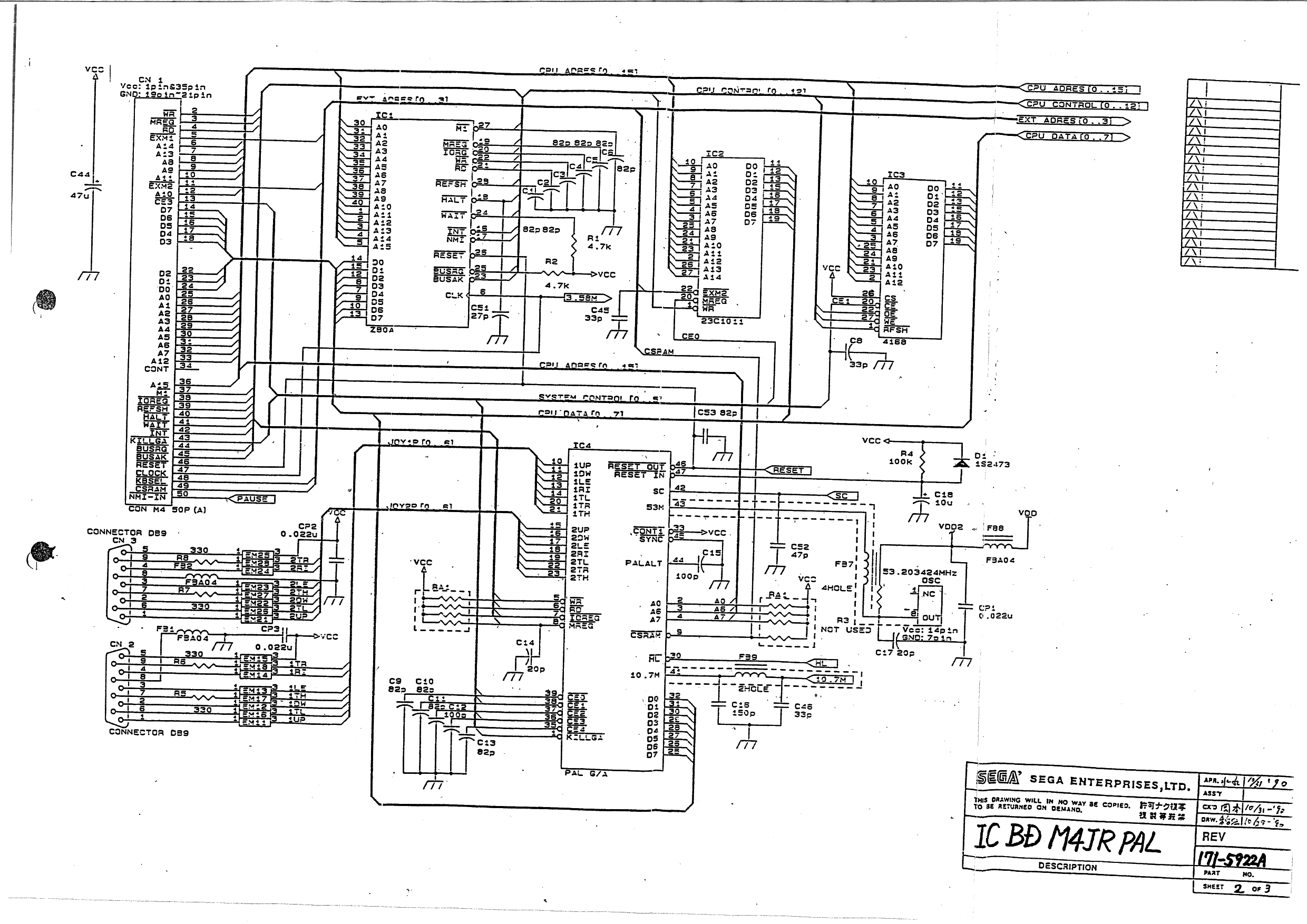
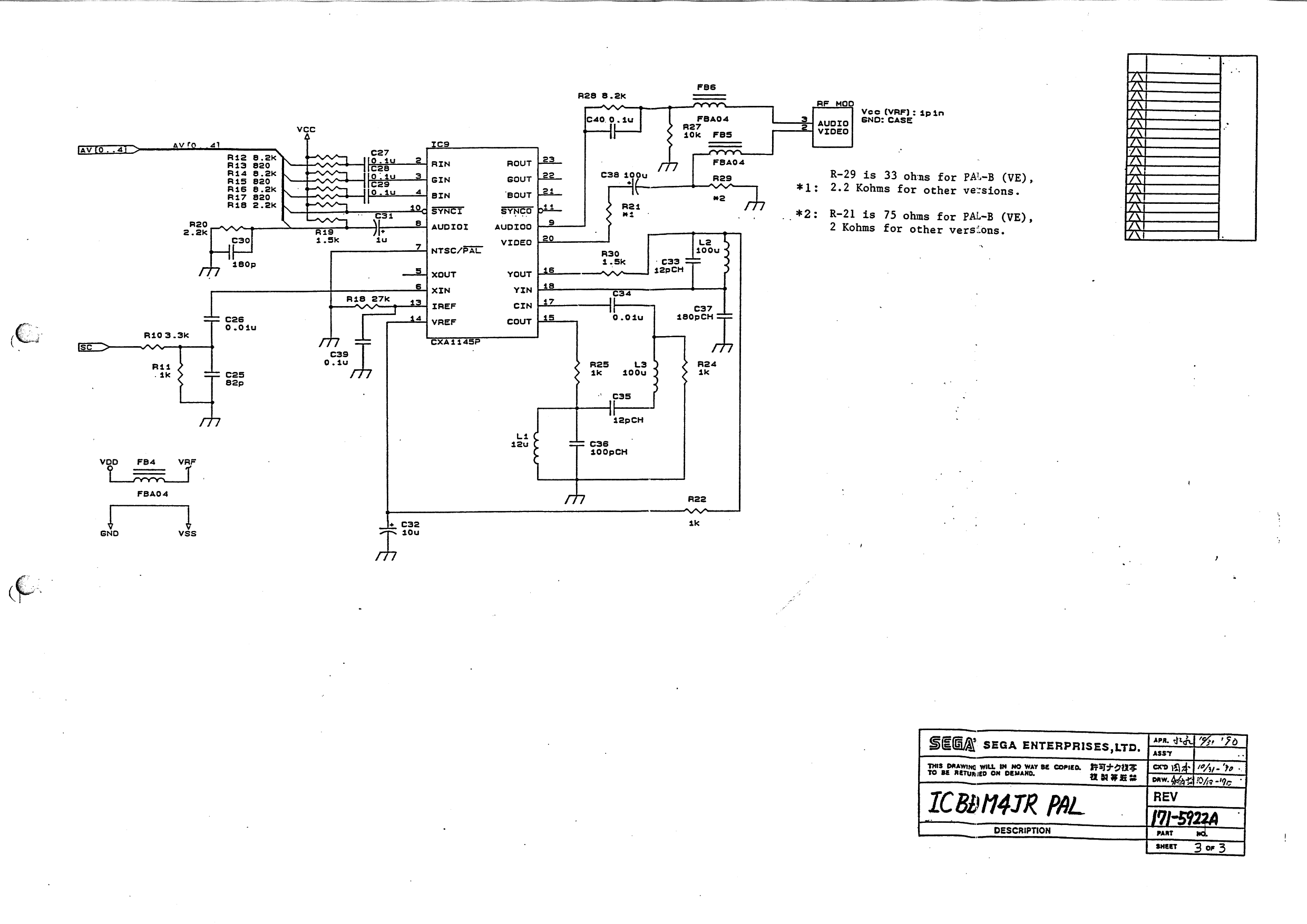
Schematic Diagram For Master System II PAL Version
IC BD M4JR PAL 171-5922A

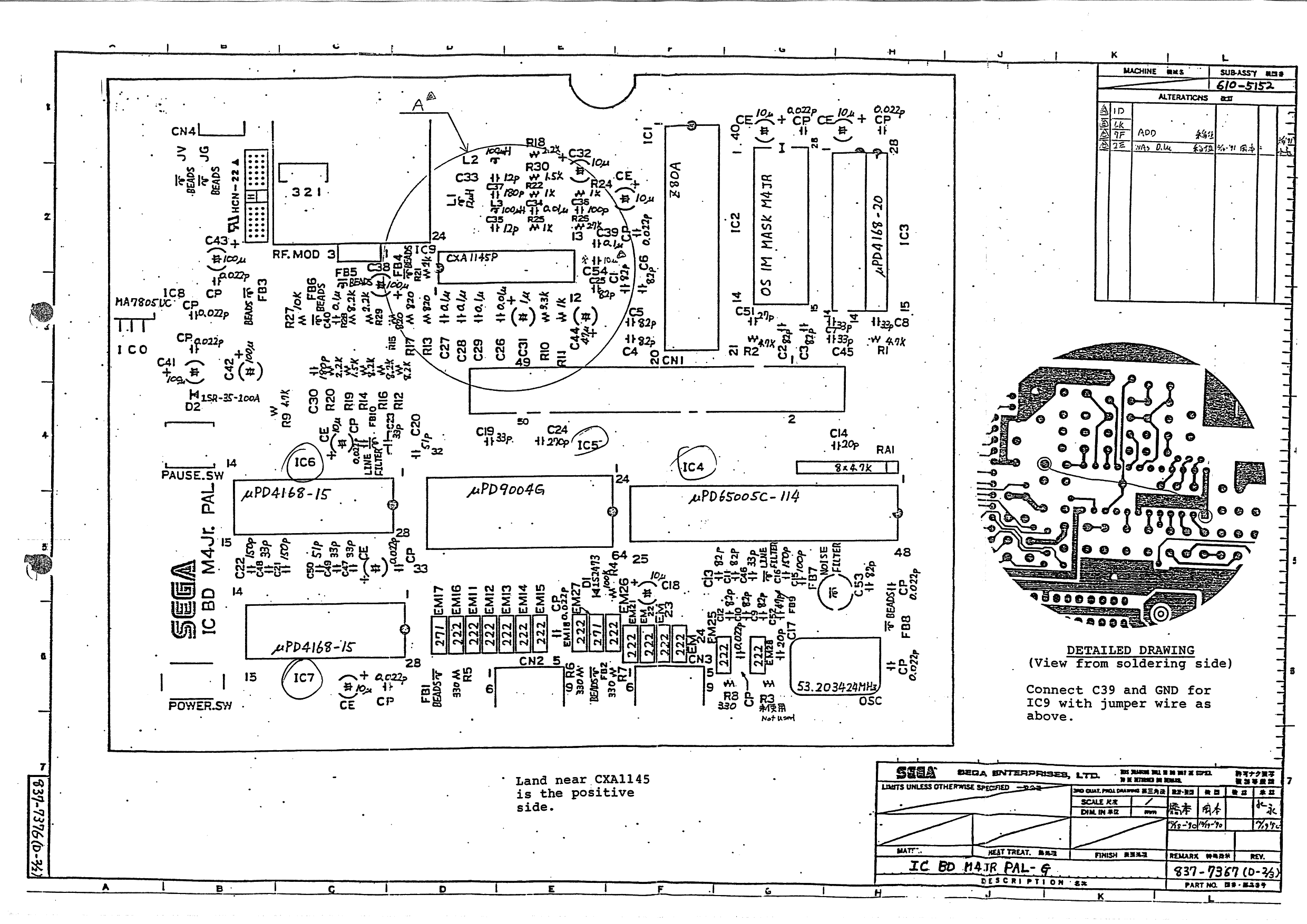
IC BD M4JR PAL-G 837-7367
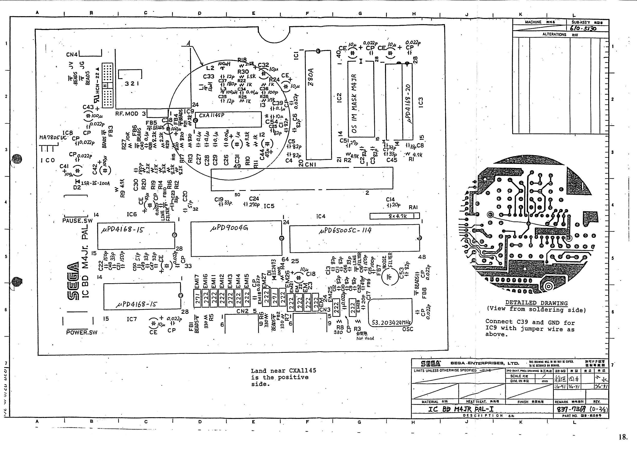
IC BD M4JR PAL-I 837-7369
IC BD M4JR PAL-B (VV) 837-7370

IC BD M4JR PAL-B (VE) 837-7371
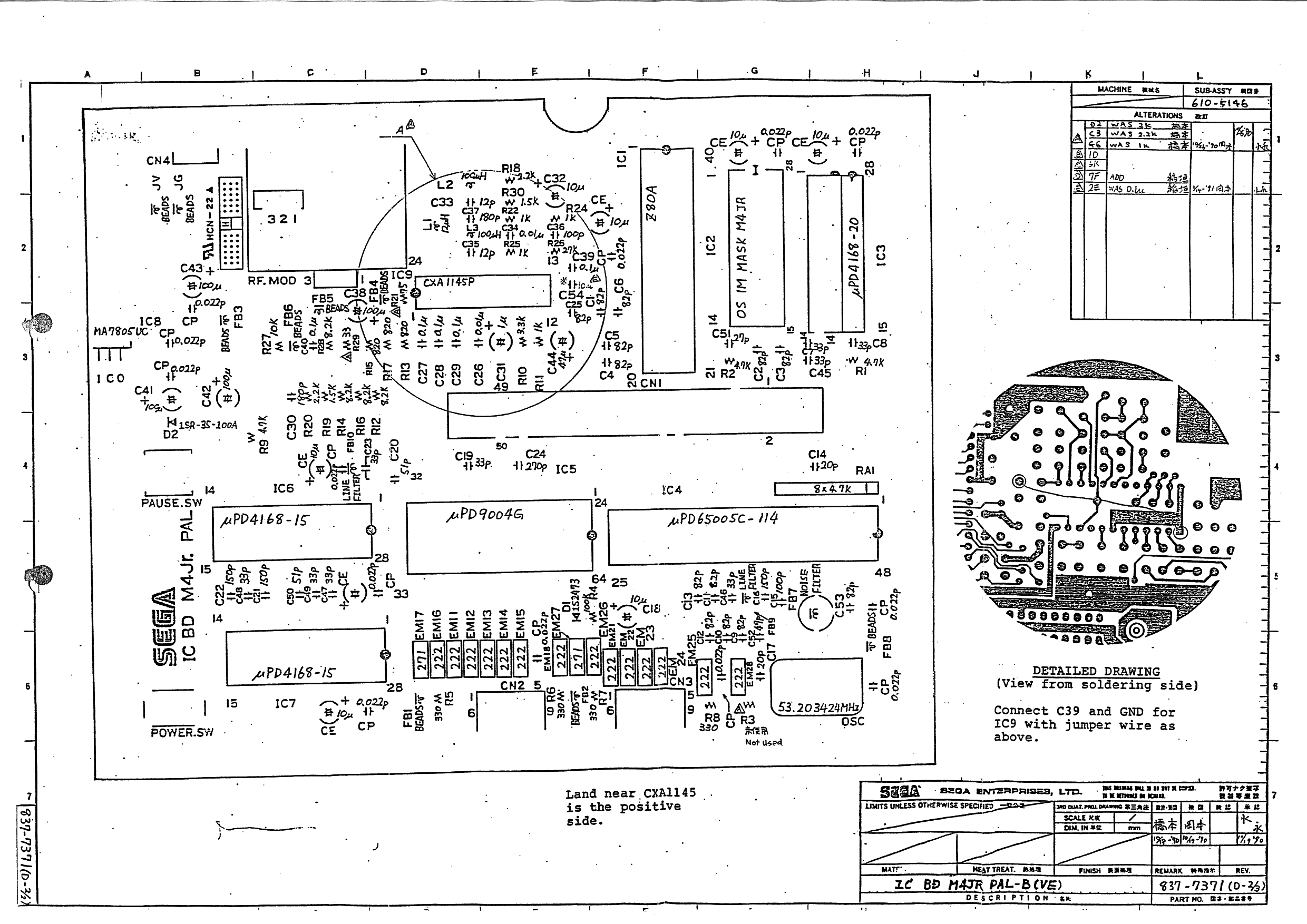
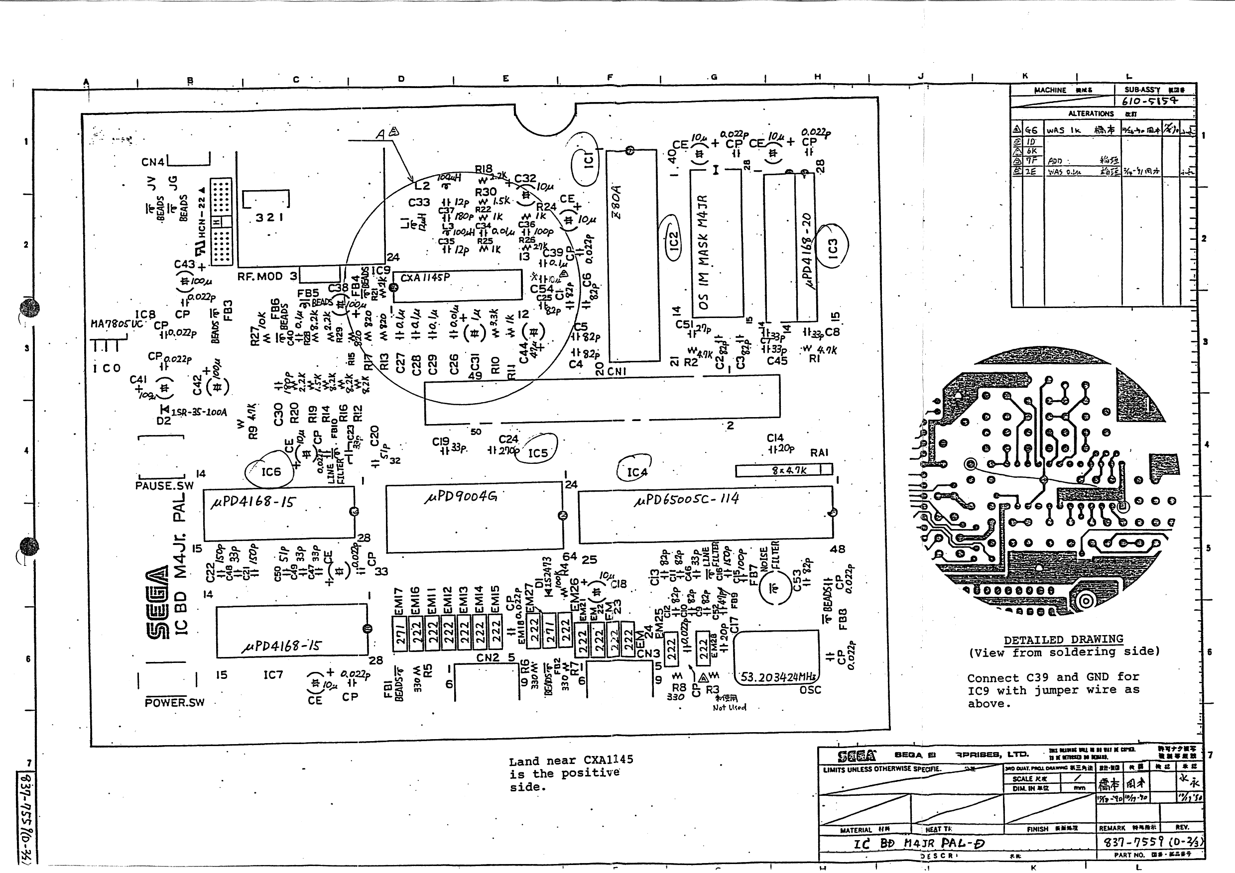
IC BD M4JR PAL-D 837-7559
Parts List For Master System II PAL Version
| LOCATION | PART NUMBER | DESCRIPTION |
|---|---|---|
| AC ADAPTOR | 400-5130 | AC ADAPTOR AC240-/DC9V 0.5A (Australia) |
| AC ADAPTOR | 400-5126 | AC ADAPTOR AC 220V/DC9V 0.5A (Europe) |
| AC ADAPTOR | 400-5129 | AC 240V/DC9V 0.5A(UK) |
| RF. MOD. | 200-5091-A | RF MODULATOR UB 3622 (I-PAL) |
| RF. MOD. | 200-5198 | RF MODULATOR VE 3423 (B-PAL VE) |
| RF. MOD. | 200-5086 | RF MODULATOR UE 3622 (G-PAL) |
| 610-5127 | ASSY CONTROL PAD 3020-03 | |
| 610-5128 | ASSY RF SW BOX W/RF CABLE | |
| 671-1215 | SUPPORT BOARD MS2 MULTI | |
| 601-6681 | STYROFOAM MS2 MULTI UR | |
| 671-1155 | BOXC MS2 BLACK MULTI | |
| 671-1156 | MA CTNMS2 MULTI | |
| 672-0228 | INSTR MANUAL M4 JR. MULTI | |
| 253-6426-01 | BOTTOM CASE M4 JR. BLACK PAL | |
| 250-5185 | TOP SHIELD M4 JR. | |
| 250-5186 | BOTTOM SHIELD M4 JR. | |
| 253-6425 | TOP CASE M4 JR. BLACK | |
| 253-6352 | DOOR M4 JR. | |
| 253-6427 | PAUSE SW MR JR. BLACK | |
| 253-6428 | POWER BUTTON M4 JR. BLACK | |
| PCB | 171-5922A | PC BD M4JR PAL |
| HOLDER | 250-5187 | HOLDER M4JR |
| CN1 | 209-5023 | EDGE CONN 50P PSB4D25S-4R1 |
| CN2 | 209-5017 | D-SUB CONN 9P |
| CN3 | 209-5017 | D-SUB CONN 9P |
| CN4 | 212-5004 | PIN PLUG FOR DC/NP UC-0056 #1 |
| POWER SW | 509-5240-01 | SLIDE SW HSW1699-01-010 |
| PAUSE SW | 509-5207 | TACT SW SKEVAA |
| PAUSE SW | 510-5019 | TACTILE PUSH SW SKEVAA |
| IC1 | 315-0041 | ICZ80A |
| IC2 | MPR-12808 | IC OS 1M MASK M4 JR |
| IC3 | 315-0298 | IC UPD4168C-20 |
| IC4 | 315-5237 | IC GA UPD65005C-114 |
| 1C5 | 315-5246 | 1C CUSTOM CHIP UPD9004G |
| IC6, IC7 | 315-0298-15 | IC UPD4168C-15 |
| IC8 | 313-0092 | IC MA7805UC |
| IC9 | 313-5067 | ICCXA1145P |
| D1 | 481-0149-01 | DIODE 1S2473 |
| D2 | 481-5038-01 | DIODE 1SR-35-100A |
| LI | 180-5033 | PEAKING COIL 12 UH |
| L2, L3 | 180-5032 | PEAKING COIL 100UH |
| Rl, R2 | 479-0472 | RES 4.7KOHM 1/6 W |
| R9 | 479-0472 | RES 4.7 KOHm 1/6 W |
| Rll, R22, R24, R25 | 479-0102 | RES 1 KOHM 1/6 W |
| R4 | 479-0104 | RES 100 KOHM 1/6 W |
| R5, R6 | 479-0331 | RES 330 OHM 1/6 W |
| R7, R8 | 479-0331 | RES 330 OHM 1/6 W |
| RIO | 479-0332 | RES 3.3 KOHM 1/6 W |
| R12, R14, R16, R28 | 479-0822 | RES 8.2 KOHM 1/6 W |
| R13,R15, R17 | 479-0821 | RES 820 OHM 1/6 W |
| R18, R20, R29 | 479-0222 | RES 2.2 KOHM 1/6 W |
| R19, R30 | 479-0152 | RES 1.5 KOHM 1/6 W |
| R21 | 479-0202 | RES 2 KOHM 1/6 W |
| R26 | 479-0273 | RES 27 KOHM 1/6 W |
| R27 | 479-0103 | RES 10 KOHM 1/6 W |
| CI, C2, C3, C4, C5, C6, C9, CIO, Cll, C12, C13, C25, C53 | 151-0126 | CAP CER 82PF 50V |
| CI, C8, C19, C23, C45, C46, C47, C48, C49 | 151-0020 | CAP CER 33PF 50V |
| C14, C17 | 151-0021 | CAP CER 20PF 50V |
| C15 | 151-0002 | CAP CER 100PF 50V |
| C16, C21, C22 | 151-0018 | CAP CER RA 150PF 50V |
| C18, C32, CEl, CE2, CE3, CE4, CE5, CE6 | 150-0023 | CAP E 10UF 16V |
| C20, C50 | 151-0072 | CAP CER 51PF 50V |
| C24 | 151-0156 | CAP CER 270PF 50V |
| C26, 34 | 151-0011 | CAP CER 0.01 UF 50V |
| C27, C28, C29, C39, C40, C54 | 151-0060 | CAP CER 0.1 UF 16V |
| C30 | 151-0075 | CAP CER RA 180PF 50V |
| C31 | 150-0009 | CAP E 1UF 50V |
| C33, C35 | 151-0190 | CAP CER 12PF 50V |
| C36 | 151-0159 | CAP CER RA 100PF 50V |
| C37 | 151-0172 | CAP CER 180PF 50V |
| C38, C42, C43 | 150-0047 | CAP E 100UF 10V |
| C41 | 150-0059 | CAP E 100UF 16V |
| C44 | 150-0062 | CAP E 47UF 10V |
| C51 | 151-0287 | CAP CER 27PF 50V |
| C52 | 151-0079 | CAP CER 47PF 50V |
| CPl, CP2, CP3, CP4, CP5, CP6, CP7, CP8, CP9, CPIO, CP11, CP 12, CPl3 | 151-0170 | CAP CER AX 0.022UF 16V |
| FBI, FB2, FB3, FB4, FB5, FB6, FB8, JV, JG | 271-0005-1 | BEADS INDUCTOR FBA04VA600VB-00 |
| FB7 | 270-5027 | LINE FILTER |
| FB9, FBIO | 270-5035 | LINE FILTER FBR07HA121 |
| EM11, EM12, EM13, EM14, EM15, EM16, EM18, EM21, EM22, EM23, EM24, EM25, EM26, EM28 | 271-0007 | EMI FILTER STX222MB |
| EM 17, EM27 | 271-0006 | EMI FILTER STB271KB |
| OSC | 230-5058 | OSC 53.203424M 20PPM |
| RA1 | 477-0005 | RES PACK 8*4.7K (RA8-4728K) |
| GRS | 601-0076 | TML JNT CMPD 200G/TUBE (AMICOM) |
Schematic Diagram For Master System II RGB Version
IC BD M4 Jr. RGB 171-5926

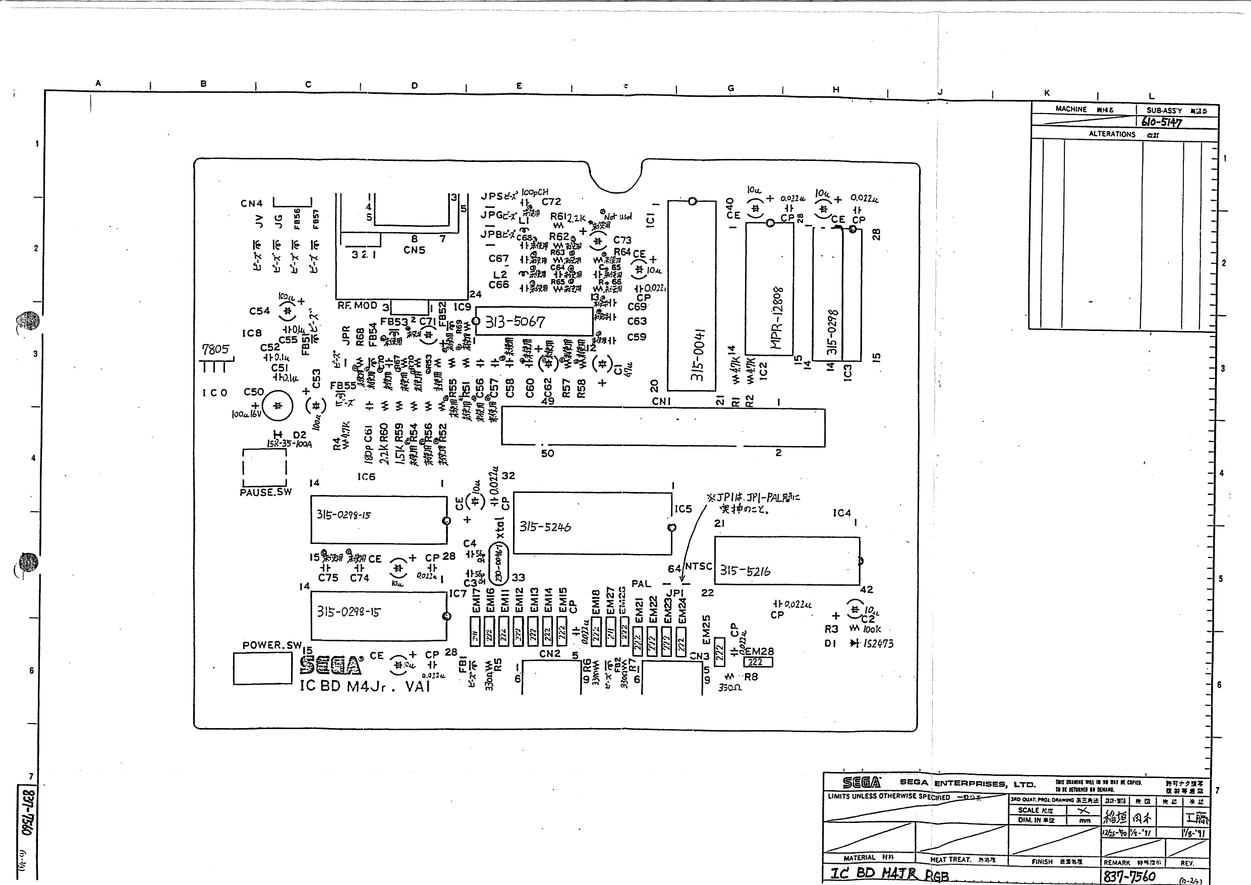
IC BD M4JR RGB 837-7560
Parts List For Master System II RGB Version
| LOCATION | PART NUMBER | DESCRIPTION |
|---|---|---|
| 610-5127 | ASSY CONTROL PAD 3020-03 | |
| 400-5048Y | AC ADAPTOR AC220V/DC9V 1A | |
| 610-0130 | RGB BOX FRANCE | |
| 671-1215 | SUPPORT BOARD MS2 MULT1 | |
| 601-6681 | STYROFOAM MS2 MULTI UK | |
| 671-1155 | BOX MS2 BLACK MULTI | |
| 671-1156 | MA CTNMS2 MULTI | |
| 672-0228 | INSTR MANUAL M4 JR. MULTI | |
| 253-6426-02 | BOTrOM CASE M4 JR. BLACK RGB | |
| 250-5185 | TOP SHIELD M4 JR. | |
| 250-5186 | BOTTOM SHIELD M4 JR. | |
| 670-0835 | SEAL SER. NO. M4 JR. RGB | |
| 253-6425 | TOP CASE M4 JR. BLACK | |
| 253-6352 | DOOR M4 JR. | |
| 253-6427 | PAUSE SW MR JR. BLACK | |
| 253-6428 | POWER BUTTON M4 JR. BLACK | |
| PCB | 171-5926A | PC BDM4JRVA1 |
| CN1 | 209-5023 | EDGE CONN 50P PSB4D25S-4R1 |
| CN2, CN3 | 209-5017-01 | D-SUB 9P ANGLE TYPE UC-0060 #2 |
| CN4 | 221-5004 | PIN PLUG FOR DC/NP UC-0056#1 |
| CN5 | 212-5106 | DIN CONN B-TYPE UC-0059#2 |
| POWER SW | 509-5240-01 | SLIDE SW HSW1699-01-010 |
| PAUSE SW | 509-5207 | TACT SW SKEVAA |
| PAUSE SW | 510-5019 | TACTILE PUSH SW SKEVAA |
| IC1 | 315-0041 | ICZ80A |
| IC2 | MPR-12808 | ICOS 1MMASKM4JR |
| IC3 | 315-0298 | IC UPD4168C-20 |
| IC4 | 315-5216 | IC CUSTOM CHIP G/A |
| IC5 | 315-5246 | IC CUSTOM CHIP UPD9004G |
| IC6, IC7 | 315-0298-15 | IC UPD4168C-15 |
| 1C8 | 313-0092 | IC MA7805UC |
| D1 | 481-0149-01 | DIODE 1S2473 RADIAL |
| D2 | 481-5038-01 | DIODE 1SR-35-100A RADIAL |
| Rl, R2 | 479-0472 | RES 4.7 KOHM 1/6 W |
| R3 | 479-0104 | RES 100 KOHM 1/6 W |
| R4 | 479-0472 | RES 4.7 KOHM 1/6 W |
| R5, R6 | 479-0331 | RES 330 OHM 1/6 W |
| R7, R8 | 479-0331 | RES 330 OHM 1/6 W |
| R59 | 479-0152 | RES 1.5 KOHM 1/6 W |
| R60, R61 | 479-0222 | RES 2.2 KOHM 1/6 W |
| C1 | 150-0062 | CAPE 47UF 10V |
| C2 | 150-0023 | CAPE 10UF 16V |
| C3, C4 | 151-0279 | CAP CER 56PF 50V |
| C50 | 150-0059 | CAPE 100UF 16V |
| C51, C52 | 150-0060 | CONN 0.22MF 16V |
| C53, C54 | 150-0047 | CAPE 100UF 10V |
| C55 | 151-0060 | CAPCER 0.1 UF 16V |
| C61 | 151-0075 | CAPCERRA 180PF 50V |
| C72 | 151-0159 | CAPCERRA 100PF 50V |
| CPl, CP2, CP3, CP4, CP5, CP6, CP7, CP8, CP9, | 151-0170 | CAPCER AX 0.022UF 16V |
| CEl, CE2, CE3, CE4, CE5, CE6 | 150-0023 | CAPE 10UF 16V |
| FBI, FB2, FB51, FB55, FB56, FB67, JV, JG, JPR, JPG, JPB, JPS, | 271-0005-1 | BEADS INDUCTOR FBA04VA600VB-00 |
| X'TAL | 230-0046-1 | XTAL 10.738635 |
| EM11, EM12, EM 13, EM 14, EM 15, EM 16, EM18, EM21, EM22, EM23, EM24, EM25, EM26, EM28 | 271-0007 | EMI FILTER STX222MB |
| EM 17, EM27 | 271-0006 | EMI FILTER STB271KB |
| JP1 | 600-5061 | JUMPER WIRE 5MM |
| HOLDER | 250-5187 | HOLDER M4JR |
| GRS | 601-0076 | TML JNT CMPD 200G/TUBE (AMICON) |
| S-LOCK | 090-0012 | SCREW LOCK |
| CN2L, CN2R, CN3L, CN3R | 012-0306 TAP SCR PH 3*6 | |
| 7805-HOLDER | 029-0214 | S-T1TE SCR PH M3*8 |
| CN1L, CN1R | 048-0001 | EYLET 3.5*7 |
| DINHOLDER | 250-5013 | DIN CONN HOLDER |
