The power supply components
Having cut the Veroboard to size, we're now ready to start the building process. We begin with the power supply section, which provides a stable 5 volt supply to the ICs and to the cartridge.
The holes are referenced by their hole number and track letter(s), as explained in the previous section. Use the template you drew to find the appropriate hole.
Solder in the following components:
470uF, 35v electrolytic capacitor
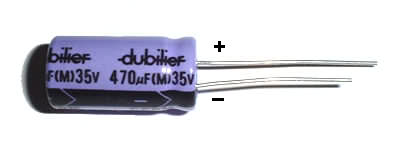
- Positive terminal
- 10D
- Negative terminal
- 10B
Ensure the capacitor is flush with the board. Note that it's very important that you get the terminals the right way round - electrolytic capacitors have a habit of exploding rather nastily when their polarity is reversed, which could cause you serious harm if you're anywhere in the vicinity.
1N4001 Rectifier Diode
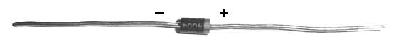
- Positive terminal
- 5D
- Negative terminal
- 8E
220nF Ceramic Capacitor
Connect between 13B and 13D.
7805 Voltage Regulator
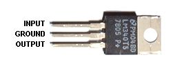
Bend the pins of the regulator and solder them into the following holes:
- Input pin
- 17D
- Ground pin
- 16B
- Output pin
- 15C
The regulator should be mounted vertically (i.e. perpendicular) and as close to the board as possible.
22uF Tantalum Capacitor
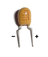
- Negative terminal
- 18B
- Positive terminal
- 20C
As with the electrolytic capacitor, make sure you get the terminals the right way round.
Cutting Tracks
Now, as described in the previous section, we must cut some tracks to break circuit connections. Take your track cutter and drill the following holes:
- 9E
- 19D
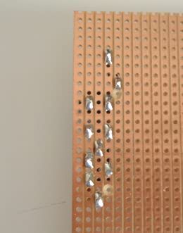
Progress So Far...
All being well, your board should now look something like this:

< Preparing the board | SMSReader | Sockets >